S&C Instruction Sheet 461-507 9
Operation
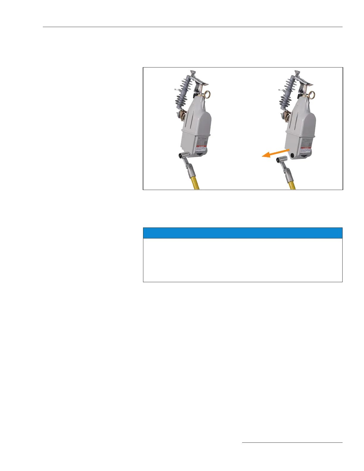
STEP 5. As the magnet tool gets closer, the magnet will be attracted
automatically to the green S&C logo and attach to the recloser. The
magnet must cover the entire logo area. As soon as the magnet is
attached to the green S&C logo, move the hotstick away. See Figure 5.
Figure 5. Attaching the magnet and moving the magnet tool away from the recloser.
When the magnet is attached and the TripSaver II recloser is powered by load
current, communicate with the TripSaver II recloser in the eld using the TripSaver
II Service Center Conguration Software.
NOTICE
To power a TripSaver II recloser from its Sleep state, there must be enough load
current available (1 A for 40-A continuous reclosers, 4 A for 100-A continuous
reclosers, and 8 A for 200-A continuous reclosers). When powered, the control
can stay on as long as the power does not fall below the Stay On threshold
(0.5 A for 40-A continuous reclosers, 1.5 A for 100-A continuous reclosers, and 3
A for 200-A continuous reclosers).

 Loading...


