EasyManuals Logo

S&C Vista Series User Manual

S&C Vista Series
27 pages
To Next Page IconTo Next Page
To Previous Page IconTo Previous Page
Page #18 background imageLoading...
Page #18 background image
18 S&C Instruction Sheet 681-510
Operation
(c) If the dot or any of the  ashing lightning
bolts
do not appear, make sure the TEST
button is completely covered with a gloved
nger so no light shines on the photoreceptor
and there is adequate light (provided either
by a  ashlight or the sun) to power the test
circuit. If the dot
or any of the  ashing
lightning bolts
still do not appear, the
VOLTAGE indicator may be damaged. Test
for voltage using an alternate method.
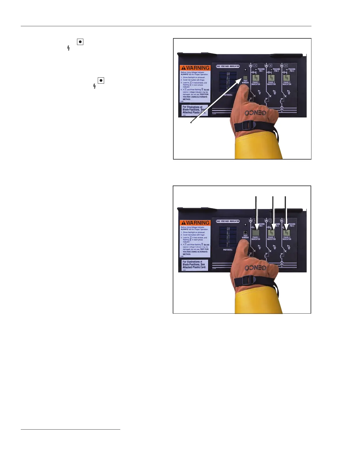
See Figures 34 and 35.
PHASE indicators
Figure 35. If one or more PHASE indicators does not show a
flashing lightning bolt during testing, the VOLTAGE indicator
may be damaged. Test for voltage using an alternate method.
Figure 34. The absence of a dot in the Test window indicates
the VOLTAGE indicator is not in Test mode.
Test window

Questions and Answers:

Question and Answer IconNeed help?

Do you have a question about the S&C Vista Series and is the answer not in the manual?

S&C Vista Series Specifications

General IconGeneral
Voltage RatingUp to 38 kV
Continuous Current600 A
Frequency60 Hz
Interrupting RatingUp to 25 kA
Interrupting Current20 kA, 25 kA
BIL95 kV, 125 kV, 150 kV
Insulation MediumSF6
Enclosure TypeMetal-clad or Metal-enclosed
Number of Ways2, 3, 4, 5, or 6
Switching MechanismVacuum Interrupters
Operating MechanismManual
Standards ComplianceIEEE C37.60
Fault InterruptionYes

Related product manuals