S&C Instruction Sheet 681-510 19
Operation
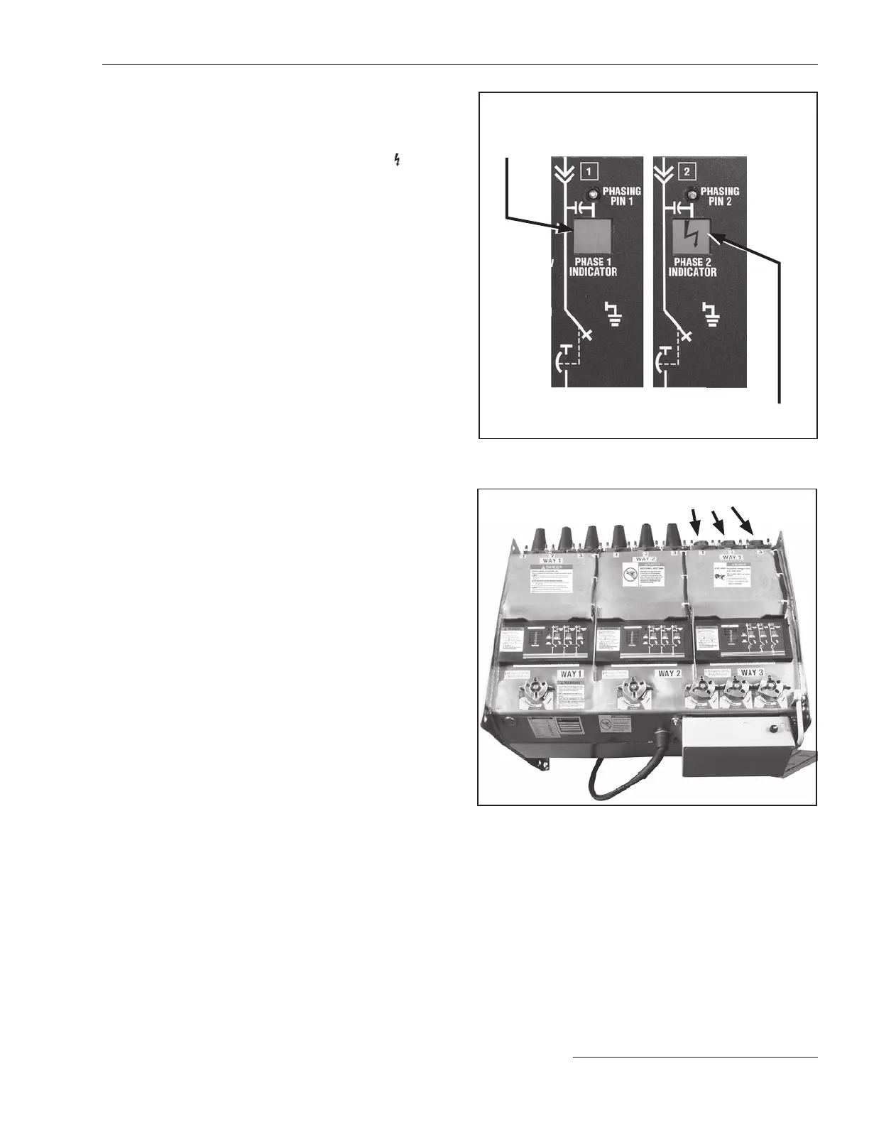
STEP 3. Check the PHASE indicators for the desired
phases of the load-interrupter switch or fault
interrupter to determine whether there is any
voltage at the associated bushings. See Figures
36 and 37. A ash ing lightning bolt
in the
PHASE indicator means voltage is present at the
bush ing. A blank LCD panel means either:
• There is no voltage at the bushing.
• The VOLTAGE indicator is malfunctioning.
Flashing lightning bolt indicates presence
of voltage at the associated bushing
A blank LCD panel indicates an absence of voltage
at the associated bush ing, provided the VOLTAGE
indicator circuitry has been tested and determined
to be operating prop erly.
Figure 36. Indication of the presence or absence of voltage.
PHASE indicators show presence of voltage
at associated bushing
Figure 37. Each VOLTAGE indicator is provided with three phase
indicators—one for each phase.

 Loading...

