10 S&C Instruction Sheet 682-510
Components
OK TO
OPERATE
D
T
A
R
E
P
O
T
O
N
O
E
3
1
6
S
S
T
U
B
E
A
N
D
C
O
N
N
E
C
T
I
O
N
GAS
PRESSURE
CONFIRM
OPERATE
CONTACT S&C
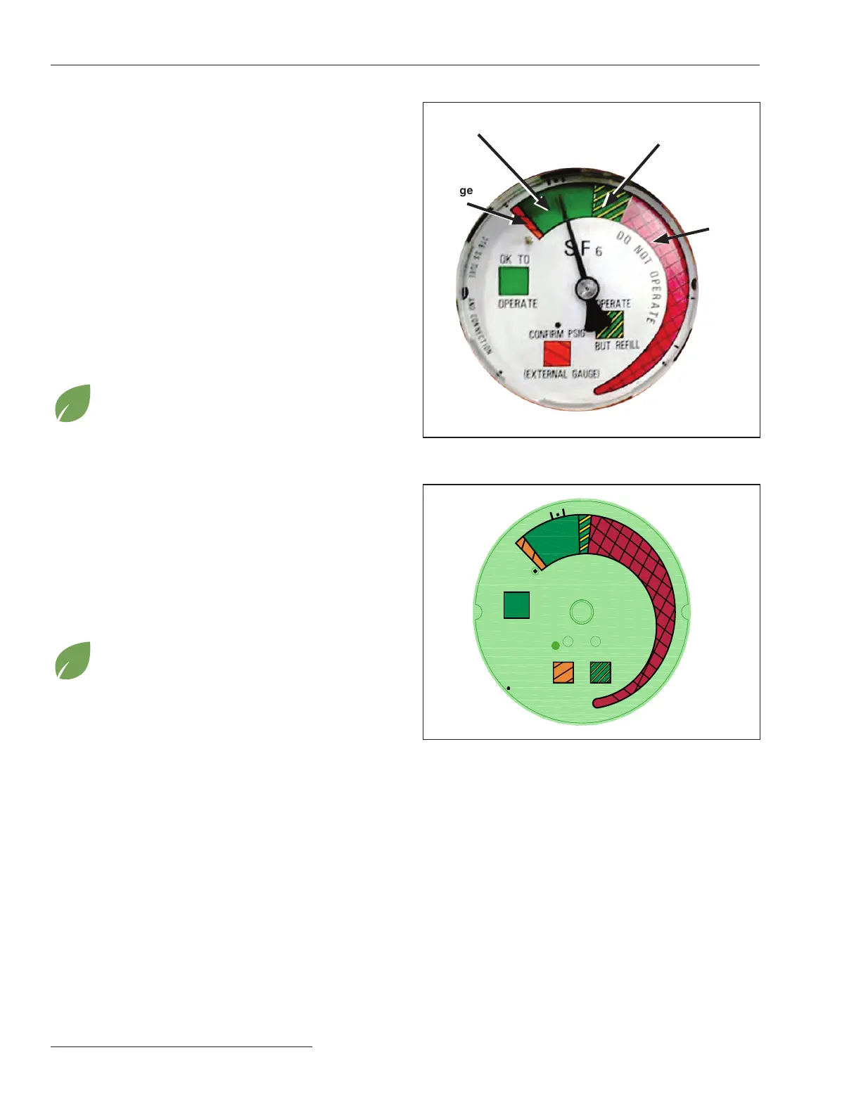
Understanding the Gas-Pressure Gauge
Vista switchgear incorporates a temperature-compensated
gas-pressure gauge inside the tank to provide indication of
the insulating-gas pressure. The gas-pressure gauge includes
four distinct color-coded zones. See Figures 8 and 9.
If the needle is within a particular zone as described
below, it indicates the following:
Green zone:
The Vista switchgear unit is OK to operate.
Green/Yellow zone:
The Vista switchgear unit may have lost some gas but is
still OK to operate. For SF
6
models: The unit should be
evaluated to determine whether it needs to be relled with
SF
6
gas via the eld-accessible ll port and repaired accord-
ingly. Contact S&C for assistance.
Vista Green switchgear models are hermetically
sealed. The gas-ll port is not accessible in the
eld as standard. Contact S&C for assistance.
Red zone:
The insulating gas may be below the minimum operating
pressure for the gear. Vista switchgear should not be
operated if the needle is in the Red zone. Contact S&C
Electric Company for assistance.
Orange zone:
The Vista switchgear unit has been overlled or has a defec-
tive pressure gauge. For SF
6
models and eld-accessible
ports, an external gauge can be used instead to verify the
gas pressure before operation of the device. Contact S&C
for assistance.
Vista Green switchgear models are hermetically
sealed. The gas-ll port is not accessible in the
eld as standard. Contact S&C for assistance.
Figure 8� The internal gas-pressure gauge for most SF
6
models�
Figure 9� The internal gas-pressure gauge for Vista Green
switchgear models, “-GRN” catalog numbers�
Red
zone
Green/ Yellow
zone
Green
zone
Orange
zone

 Loading...

