S&C Instruction Sheet 682-510 9
Components
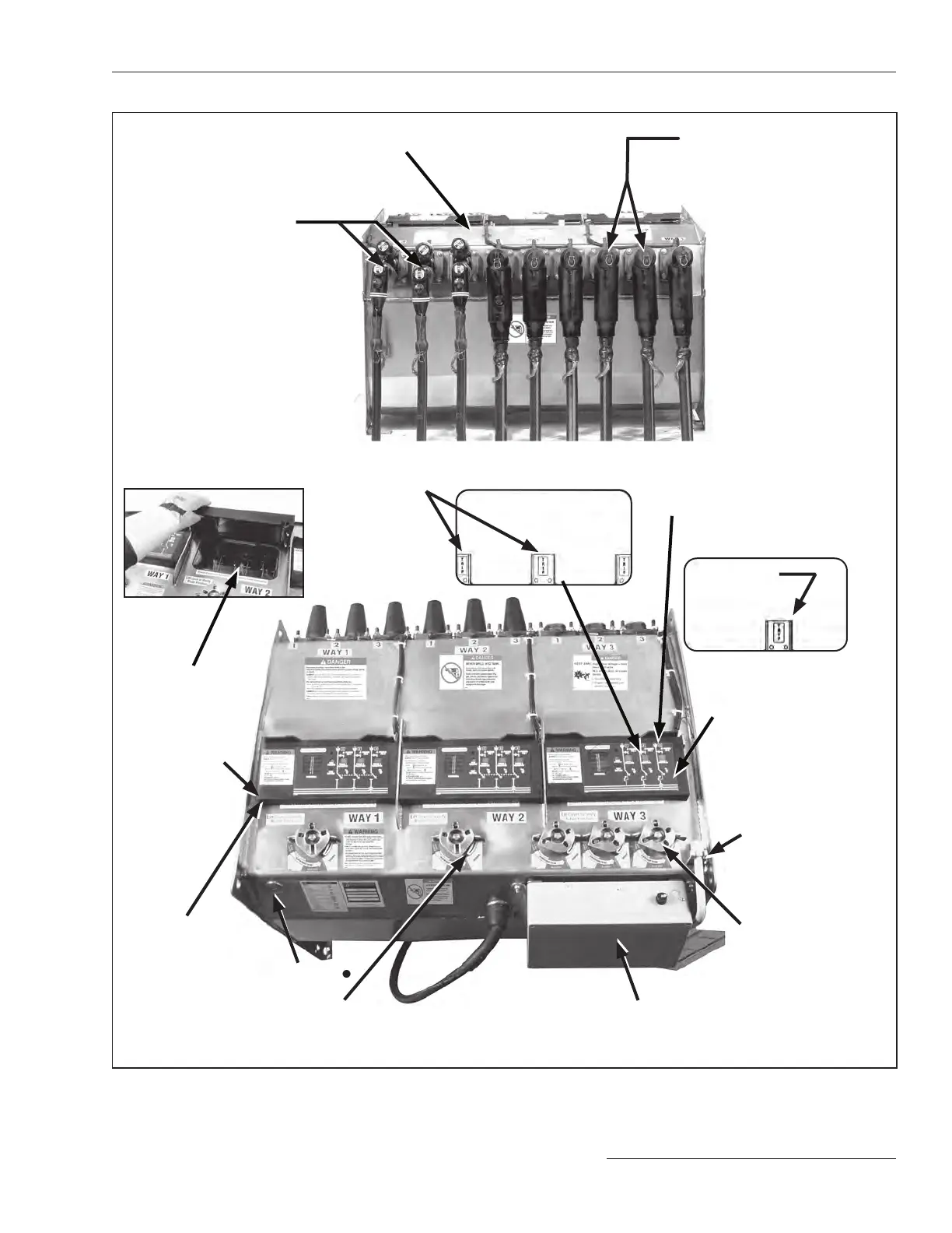
Figure 7� The termination side and top of switchgear�
Top of
switchgear
Optional VOLTAGE indica-
tor with phasing (option
suffix “-L2”) includes
liq uid-crystal display
indicating when voltage is
present
Insulating-gas
pressure gauge is
located inside the tank
and is visible through
the viewing window
Gas-fill port●
Operating mechanism
is padlockable in any
position
Viewing window
allows operator
to see open gap,
Grounded position,
and bus ground of
the load-interrupter
switch or fault
interrupter
Operation selector prevents inad vertent
operation from the Closed position directly
to the Grounded position, and vice versa
S&C overcurrent control
Manual operating
handle
Viewing window under the
VOLTAGE indicator
TRIP indicators
for single-pole
fault interrupters
TRIP indicator
for three-pole
fault
interrupters
Fault-interrupter terminals
are equipped with 200-ampere
bushing wells� Optional
600-ampere bushings (option
suffix “-M2” or “-M3”) are available
Submersible tank Switch terminals are equipped
with 600-ampere bushings or
optional 200-amp bushing wells
Termination side of switchgear
●The gas-fill port is field-accessible for SF
6
models� For Vista Green switchgear models, the gas-fill port is designed to prevent field-refilling�
 Loading...


