8 S&C Instruction Sheet 682-510
Components
Figure 4� The Open position indication on the motor
operator�
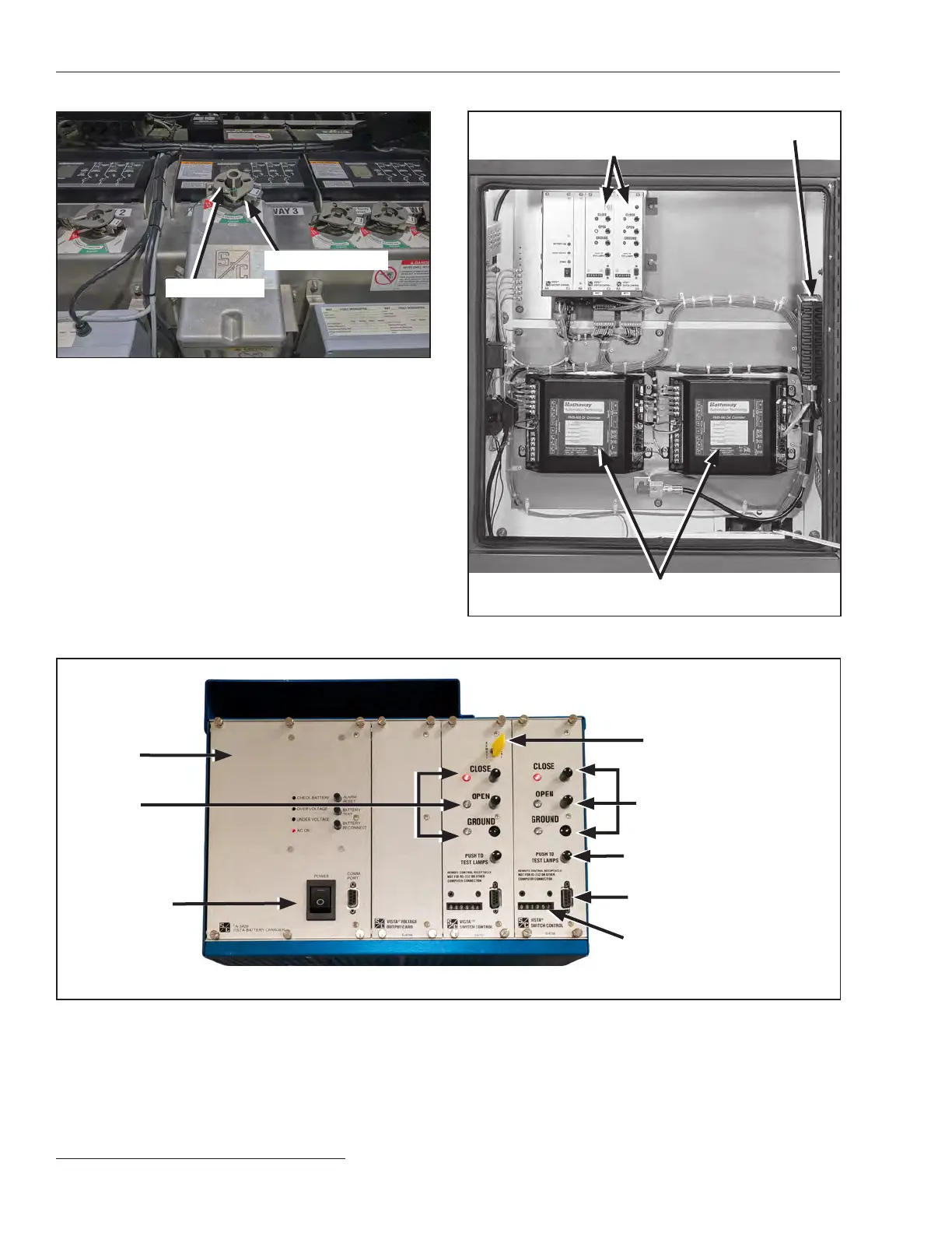
Figure 6� The motor operator control rack�
Operation
counter
PUSH-TO-TEST
LAMPS button
Receptacle for portable
remote control
Operation pushbuttons
Battery
charger
LOCAL/REMOTE switch
Position-
indicating
LEDs
Figure 5� The low-voltage enclosure�
User-specified RTUs (optional)
User-specified communi cation
device (optional)
Motor operator
control boards
POWER switch
Operation selector
Operating disk
 Loading...


