S&C Instruction Sheet 682-510 7
Components
Overview of Components
Remote supervisory Vista Underground Distribution
Switchgear features load-interrupter switches for switch-
ing 600-ampere main feeders; microprocessor-controlled,
resettable, vacuum fault interrupters for switching and
protection of 600-ampere main feeders; and 200-ampere
taps, laterals, and subloops. These elbow-connected
components are enclosed in a submersible, gas-insulated,
hermetically sealed welded-steel tank.
The three-position (CLOSED/OPEN/GROUNDED) load-
interrupter switches are manually operated and provide
three-pole live switching of 600-ampere three-phase
circuits. These switches also provide a visible gap when
open and internal grounding for all three phases. When
they are fitted with motor operators and controls, these
switches can be electrically oper ated via local operation
pushbuttons. The user may also control the motor opera-
tors for the load-interrupter switches remotely when a
remote termi nal unit (RTU) and communication device
are integrated with the remote supervisory Vista motor
operators and controls.
The 200-ampere and 600-ampere fault interrupters
feature resettable vacuum interrupters in series with
manually operated three-position (CLOSED/OPEN/
GROUNDED) disconnects for isolation and internal
ground ing of each phase. Fault interrupters provide single-
pole or three-pole fault interruption and manual single-pole
(standard) or three-pole (optional) live switching of load
circuits. Fault interruption is initiated by a programma-
ble overcurrent control. Conversion from single-pole trip
control to three-pole trip control is accomplished using a
personal computer. See S&C Instruc tion Sheet 681-530
for instructions on programming the control. The
three-pole fault interrupters may be fitted with motor
operators and con trols so they may be electrically operated
via local operation pushbut tons. The user may also control
the motor operators for the three-pole fault interrupters
remotely when an RTU and a communi cation device are
integrated with the remote supervisory Vista motor opera-
tor and controls.
When the optional voltage indicator (option suffix
“-L1” or “-L2”) is spec ified, all routine operating tasks—
switching, voltage testing, and ground ing—can be
accomplished by a single person without cable handling
or exposure to high voltage. Cable testing for faults can
be performed through the back of a user-supplied elbow
with an insert or feedthrough bushing insert, eliminating
the need for cable handling or parking stands. Refer to
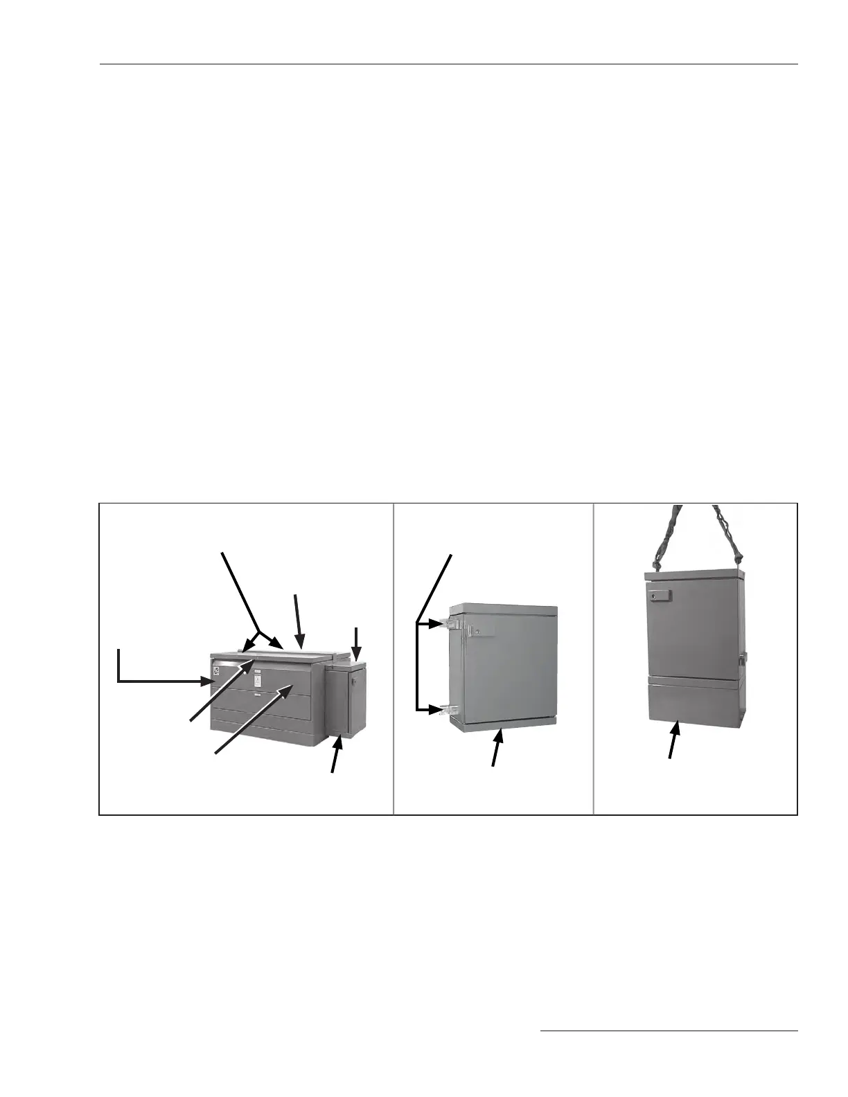
Figures 1 through 7 on pages 7 through 9 for the location
of components.
Figure 3� Wet-vault and
UnderCover™ Style gear low-volt-
age enclosure�
Mounting brackets for mounting
enclosure to a wall or on a post
S&C’s Ultradur II
Outdoor Finish
S&C’s Ultradur® II
Outdoor Finish
S&C’s Ultradur II
Outdoor Finish
Figure 2� Dry-vault-mounted
style gear low-voltage
enclo sure�
Operation compartment
Termination
compartment
Low-voltage
compartment
Removable panel for
access to viewing
windows and operating
mechanisms
Padlockable hinged roofs for access to operation
and termination compartments
Figure 1� Pad-mounted style gear�
Pentahead bolt