7/05 Model HDB2-A Page 3 Rev B
The diaphragm assemblies are to be installed with the natural bulge outward or
toward the head of the center screw. Make sure both plates are installed with outer
radii against the diaphragm. After all components are in position in a vise and hand
tight, set a torque wrench for 40 ft. pounds (54.23 Newton meters) using a 1
1
/8" (2.857
cm) socket. After each diaphragm sub assembly has been completed, thread one
assembly into the diaphragm rod. Make sure the 5/16-18 UNC capscrew has been
removed from the inner plate and the diaphragm rod bumper is in place on the
diaphragm rod.
Install this sub assembly into the pump and secure by installing the outer chamber
in place and tightening the capscrews. This will hold the assembly in place while the
opposite side is installed. Install the second diaphragm assembly into the diaphragm
rod checking to see that the diaphragm rod bumper is in place. Tighten to 30 ft. lbs.
(40.67 Newton meters) torque before installing the outer chamber in place. If the holes
in the diaphragm flange do not align with the holes in the inner chamber flange, turn
the diaphragm assembly in the direction of tightening to align the holes so that the
capscrews can be inserted. This final torquing of the last diaphragm assembly will lock
the two diaphragm assemblies together. Secure the last
outer chamber by tightening down the securing nuts
gradually and evenly. This tightening procedure should
be done on both sides.
When reinstalling check valves, take care that the
seat gaskets are aligned properly before securing
porting flange in place.
A Note about Air Valve Lubrication
The SANDPIPER pump’s pilot valve and main air valve
assemblies are designed to operate WITHOUT
lubrication. This is the preferred mode of operation. There
may be instances of personal preference, or poor quality air supplies when lubrication
of the compressed air supply is required. The pump air system will operate with properly
lubricated compressed air supplies. Proper lubrication of the compressed air supply
would entail the use of an air line lubricator (available from Warren Rupp) set to deliver
one drop of 10 wt., non-detergent oil for every 20 SCFM of air the pump consumed at its
point of operation. Consult the pump’s published Performance Curve to determine this.
It is important to remember to inspect the sleeve and spool set routinely. It should
move back and forth freely. This is most important when the air supply is lubricated.
If a lubricator is used, oil accumulation will, over time, collect any debris from the
compressed air. This can prevent the pump from operating properly.
Water in the compressed air supply can create problems such as icing or freezing
of the exhaust air causing the pump to cycle erratically, or stop operating. This can be
addressed by using a point of use air dryer to supplement a plant’s air drying
equipment. This device will remove excess water from the compressed air supply and
alleviate the icing or freezing problem.
ESADS: Externally Serviceable Air Distribution System
Please refer to the exploded view drawing and parts list in the Service Manual
supplied with your pump. If you need replacement or additional copies, contact your
local Warren Rupp Distributor, or the Warren Rupp factory Literature Department at
the number shown below. To receive the correct manual, you must specify the MODEL
and TYPE information found on the name plate of the pump.
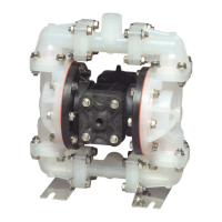
The main air valve sleeve and spool set is located in the valve body mounted on
the pump with four hex head capscrews. The valve body assembly is removed from
the pump by removing these four hex head capscrews.
With the valve body assembly off the pump, access to the sleeve and spool set is
made by removing four hex head capscrews (each end) on the end caps of the valve
body assembly. With the end caps removed, slide the spool back and forth in the
sleeve. The spool is closely sized to the sleeve and must move freely to allow for proper
pump operation. An accumulation of oil, dirt or other contaminants from the pump’s
air supply, or from a failed diaphragm, may prevent the spool from moving freely. This
can cause the spool to stick in a position that prevents the pump from operating. If this
is the case, the sleeve and spool set should be removed from the valve body for
cleaning and further inspection.
DANGER
Before doing any maintenance on
the pump, be certain all pressure
is completely vented from the
pump, suction, discharge, piping,
and all other openings and
connections. Be certain the air supply
is locked out or made nonoperational,
so that it cannot be started while
work is being done on the pump. Be
certain that approved eye protection
and protective clothing are worn at
all times in the vicinity of the pump.
Failure to follow these
recommendations may result in serious
injury or death.
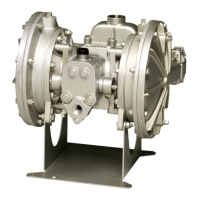
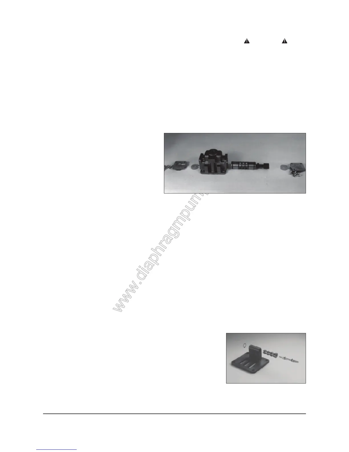
Pilot valve.
Air valve body.
 Loading...