SERVICE & OPERATING MANUAL
WARREN RUPP
®
, INC. • A Unit of IDEX Corporation • P.O. Box 1568, Mansfield, Ohio 44901-1568 USA • Telephone (419) 524-8388 • Fax (419) 522-7867 • www.warrenrupp.com
520-209-000 9/03
©Copyright 2003 Warren Rupp, Inc. All rights reserved.
®
Engineering Data and Temperature Limitations ...................................................................... 1
Explanation of Pump Nomenclature ........................................................................................ 2
Performance Curve, Model S20 Non-Metallic Design Level 2 ............................................... 3
Dimensions: S20 Non-Metallic ................................................................................................. 4
Metric Dimensions: S20 Non-Metallic ...................................................................................... 5
Dimensions: S20 Non-Metallic with Spill Prevention ................................................................ 6
Metric Dimensions: S20 Non-Metallic with Spill Prevention .................................................... 7
Principle of Pump Operation .................................................................................................... 8
Installation and Start-up ........................................................................................................... 8
Air Supply ................................................................................................................................. 8
Air Valve Lubrication ................................................................................................................. 8
Air Line Moisture ...................................................................................................................... 8
Air Inlet and Priming ................................................................................................................. 8
Between Uses .......................................................................................................................... 8
Installation Guide ...................................................................................................................... 9
Important Safety Information ................................................................................................. 10
Material Codes ....................................................................................................................... 10
Troubleshooting ...................................................................................................................... 11
Warranty................................................................................................................................. 11
Composite Repair Parts Drawing .......................................................................................... 12
Overlay Option Drawing ........................................................................................................ 12
Composite Repair Parts List .................................................................................................. 13
RuppGUARD™ Spill Prevention Option for Virgin PTFE Equipped Pumps ......................... 14
RuppGUARD™ Spill Prevention Repair Parts List ............................................................... 14
RuppGUARD™ Spill Prevention Concept............................................................................. 15
RuppGUARD™ Spill Prevention Option Diaphragm Servicing ............................................ 15
Filling RuppGUARD™ Chambers with Liquid ....................................................................... 15
RuppGUARD™ Spill Prevention Option for TPE Equipped Pumps ..................................... 16
RuppGUARD™ Spill Prevention Repair Parts List ............................................................... 16
RuppGUARD™ Spill Prevention Concept with TPE Diaphragms ........................................ 17
RuppGUARD™ Spill Prevention Option with TPE Diaphragm ............................................. 17
Air Distribution Valve Assembly Drawing............................................................................... 18
Main Air Valve Assembly Parts List ....................................................................................... 18
Air Distribution Valve Servicing .............................................................................................. 19
Air Distribution Valve with Stroke Indicator Options .............................................................. 20
Air Distribution Valve with Stroke Indicator Parts List ........................................................... 20
Air Distribution Valve with Stroke Indicator Servicing ........................................................... 21
Solenoid Shifted Air Valve Drawing ........................................................................................ 22
Solenoid Shifted Air Valve Parts List ...................................................................................... 22
Solenoid Shifted Air Distribution Valve option ........................................................................ 23
Pilot Valve Assembly Drawing ................................................................................................ 24
Pilot Valve Assembly Parts List.............................................................................................. 24
Pilot Valve Servicing ............................................................................................................... 25
Diaphragm Service Drawing, Non-Overlay .......................................................................... 26
Diaphragm Service Drawing, with Overlay ........................................................................... 26
Diaphragm Servicing.............................................................................................................. 27
Overlay Diaphragm Service .................................................................................................. 27
Pumping Hazardous Liquids .................................................................................................. 28
Converting the pump for piping the exhaust air .................................................................... 28
Exhaust Conversion Drawing................................................................................................ 28
Converted Exhaust Illustration .............................................................................................. 28
Modular Check Valve Servicing ............................................................................................. 29
Modular Check Valve Drawing ............................................................................................... 29
Dual Port Option Drawing ...................................................................................................... 30
Dual Porting Options .............................................................................................................. 31
Dual porting of both suction and discharge ends of the pump ............................................. 31
Single porting of the suction and dual porting of the pump discharge.................................. 31
Dual porting of the suction and single porting of the pump discharge ................................. 31
Leak Detection Options Drawing........................................................................................... 32
RuppTech® Electronic Leak Detector Installation ................................................................ 32
Mechanical Leak Detector Installation .................................................................................. 32
RuppTech® Pulse Output Kit Drawing .................................................................................. 33
RuppTech® Pulse Output Kit Option ..................................................................................... 33
Exhaust Port or Auxiliary Muffler Setup ................................................................................. 33
Integral Muffler Setup ............................................................................................................. 31
CE
U.S. Patent #
400,210
5,996,627
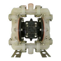
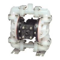
Model S20 Non-Metallic Design Level 2Model S20 Non-Metallic Design Level 2
Model S20 Non-Metallic Design Level 2Model S20 Non-Metallic Design Level 2
Model S20 Non-Metallic Design Level 2