520-202-000 9/03 Model S20 Non-Metallic Design Level 2 Page 20
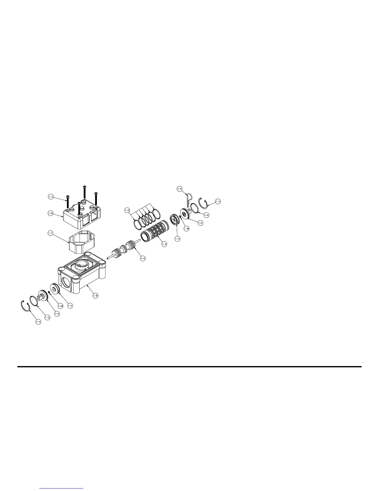
Air Valve Assembly Drawing with Stroke Indicator Option
S20 Design Level 2
Pilot Valve Assembly Parts List
Item Part Number Description Qty
1 031-146-000 Air Valve Assembly 1
1-A 031-143-000 Sleeve and Spool Set w/Pins 1
1-B 095-094-551 Body, Air Valve 1
1-C 132-029-552 Bumper 2
1-D 165-096-551 Cap, Muffler 1
1-E 165-098-147 Cap, End 2
1-F 530-028-550 Muffler 1
1-G 560-020-360 O-Ring 8
1-H 675-044-115 Ring, Retaining 2
1-J 710-015-115 Screw, Self-Tapping 4
1-K 210-008-330 Clip, Safety 1
1-M 560-029-360 O-Ring 2
For Pumps with PTFE Coated Hardware:
1 031-146-002 Air Valve Assembly 1
1-J 710-015-308 Screw, Self Tapping 4
(includes all other items on 031-146-000 above.)
For Pumps with Alternate Mesh, Sound Dampening
Mufflers or Piped Exhaust:
1 031-147-000 Air Valve Assembly 1
(includes all items on 031-146-000 minus 1-D, 1-F,
&1-J)
Note: Stroke Indicator is standard on
RuppGUARD™ Spill Prevention models