Do you have a question about the Sansui C-1000 and is the answer not in the manual?
Details input sensitivity, impedance, output level, and impedance.
Covers total harmonic distortion and frequency response characteristics.
Specifies signal-to-noise ratio and lists control functions and filters.
Lists power requirements, physical dimensions, and product weight.
Important safety notes regarding critical parts, insulation, and leakage current.
Explains symbols, market designations, and service manual abbreviations.
Lists components for F-5790, F-5791, F-5792, F-5787, F-5788, F-5789 boards.
Detailed component list for the main circuit board.
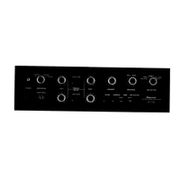
Shows component placement for control, input, power switch, volume, and logic boards.
Illustrates the component arrangement on the main circuit board.
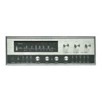
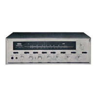
Lists parts visible on the front panel of the unit.
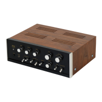
Lists parts visible on the rear panel of the unit.
Details the accessories provided with the unit.
Block diagram and terminal functions for the system control IC.
Details for analog switch, quad AND-OR gate, and OP amp ICs.
Circuit diagram for equalization and control amplifier sections.
Circuit diagram for logic control and power supply sections.
High-level diagram illustrating system signal flow.
Lists the items included in the product's packaging.