Do you have a question about the Sansui RZ-1000 and is the answer not in the manual?
Details power output, distortion, input sensitivity, S/N ratio, and controls for the audio section.
Covers tuning range, sensitivity, S/N ratio, distortion, and stereo separation for FM.
Details tuning range, sensitivity, and S/N ratio for AM reception.
Includes power requirements, dimensions, and weight of the unit.
Procedures for adjusting bias current for left and right channels of the power amplifier.
Steps for FM IF and reference frequency adjustments, including required equipment.
Explains FM SSG output attenuator types and dummy antenna circuit for FM signal feeding.
Explains the meaning of various regional certification symbols used in the manual.
Notes on the assembly status of printed circuit boards and part number indication.
Guidance on referring to the Common Parts List for omitted capacitors and resistors.
A list of abbreviations used throughout the service manual for technical terms.
Lists the parts included in the product packaging, such as bags and cases.
Details the accessories provided with the unit, like antennas and instruction manuals.
Illustrates the signal flow for the FM receiver section, including tuner, IF, and MPX.
Shows the signal processing path for AM reception, covering tuner and IF stages.
Depicts the equalizer amplifier circuit and its connections within the system.
Outlines the system control functions, including microcomputer, key matrix, and display.
Illustrates the input selection mechanism and its associated controls.
Shows the circuitry for balance, volume, bass, treble, and loudness controls.
Details the power amplifier stage, including its input and output connections.
Steps to maximize FM stereo separation and set the FM muting threshold.
Detailed steps for adjusting the AM IF coils and tuning circuits.
Procedure for setting the auto stop level for AM reception.
Lists transistors used on the F-6001 main board with part numbers and descriptions.
Lists diodes used on the F-6001 main board with part numbers and descriptions.
Lists various types of capacitors used on the F-6001 main board.
Lists inductors, IF coils, and filters for the F-6001 main board.
Lists variable resistors used on the F-6001 main board, including their function.
Lists integrated circuits used on the F-6001 main board with part numbers.
Lists additional components for the F-6001 main board.
Lists components for the F-6003 tuner control and display board.
Lists components for the F-6004 speaker impedance switch board.
Lists components for the F-6002 speaker impedance switch board.
Lists components for the F-6006 master and tone control volume board.
Lists diodes and switches for the F-6003 tuner control and operating switch board.
Shows the visual patterns displayed on the FL display for different modes and indicators.
Details the pin assignments for the FL display, mapping pins to functions and signals.
Illustrates the physical layout of components on the component side of the F-6001 main board.
Shows component placement for the power supply section on the F-6001 board.
Indicates component locations for the protector circuit on the F-6001 board.
Shows the location of fixed parts, fuses, and connectors on the F-6001 board.
Illustrates component placement for the selector section on the F-6001 board.
Shows component placement for the FM tuning and IF sections on the F-6001 board.
Illustrates component placement for the AM tuning and IF sections on the F-6001 board.
Shows component locations for the oscillator circuits on the F-6001 board.
Indicates component placement for the equalizer circuit on the F-6001 board.
Further details component placement for the power supply section on the F-6001 board.
Provides a general overview of the F-6001 main board component layout.
Shows the component layout for the F-6003 tuner control and display board.
Details the component layout for the F-6002 speaker impedance switch board.
Shows the component layout for the F-6006 master and tone control volume board.
Illustrates the component layout for the F-6007 power amplifier board.
Shows the component layout for the F-6004 speaker switch board.
Detailed schematic of the FM tuning, IF, and MPX circuits on the F-6001 board.
Detailed schematic of the AM tuning and IF circuits on the F-6001 board.
Schematic diagram of the equalizer amplifier circuit on the F-6001 board.
Schematic diagram for the input selector circuitry on the F-6001 board.
Schematic for system control, including CPU, key scan, and FL display interface.
Detailed schematic of the power supply section and its voltage regulation.
Schematic diagram of the speaker protection circuit.
Schematic for the speaker impedance selection switch board.
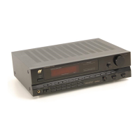
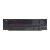
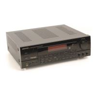
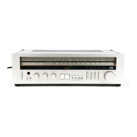
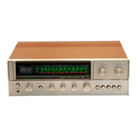
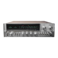
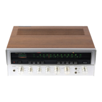
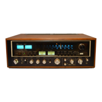
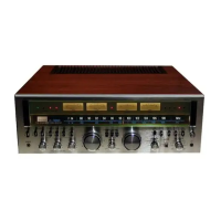
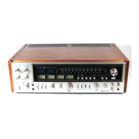
Identifies front panel controls, displays, and connectors by number.
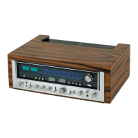
Identifies major boards and connectors visible from the top of the unit.
Block diagram and terminal functions for the LA1266 FM/AM IF and mixer IC.
Block diagram and terminal functions for the LA3410 MPX stereo decoder IC.
Block diagrams and terminal functions for the M5218 operational amplifier ICs.
Detailed pin assignments and functions for the TMP47C870N microcontroller.
Describes pins related to FL display control, signal indicator, and mute/protection outputs.
Details pins for protection input, stereo indicator, and serial interface functions.
Block diagram and terminal functions for the LC7218 PLL synthesizer IC.
Block diagram and terminal functions for the TC9163N analog switch IC.
Specific terminal functions for the LC7218 IC, including band switching and tuning signals.
Explains the ST terminal function for the TC9163N IC, related to source switching.
| Dimensions | 430 x 148 x 368mm |
|---|---|
| Weight | 11.3kg |
| Tuning range | FM, MW |
| Input Sensitivity | 2.5mV (MM), 150mV (line) |
| Signal to noise ratio | 100dB (line) |
| Speaker load impedance | 4-16 ohms |