
I
Indunil MelloJul 6, 2026
I have connect the Amp the CD and speakers but no sound
I have connect the Amp the CD and speakers but no sound
Technical specifications for amplifier output, sensitivity, and frequency response.
Technical specifications for FM and AM tuner sections, including sensitivity and distortion.
Specifications for power consumption, dimensions, and weight of the unit.
Guidelines for safe servicing, including part replacement and wiring.
Notes on handling sensitive parts, static electricity, and laser safety.
Procedures for ensuring safety insulation after repairs.
Guidance on proper disposal of batteries and electronic waste.
Equipment needed and general steps for alignment procedures.
Procedures for adjusting FM and AM tuning frequency ranges.
Steps for adjusting AM tracking sensitivity and performance.
Procedure for adjusting FM RF sensitivity and output.
Steps for adjusting FM mono distortion and THD.
Method for adjusting FM stereo signal separation.
Procedure for setting auto stop levels for FM and AM tuning.
Specific procedure for adjusting FM RDS signals, applicable to Europe.
Specific test conditions for measuring transistor and IC voltages.
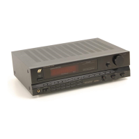
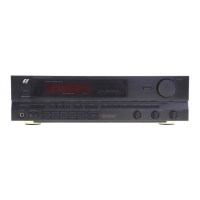
| Brand | Sansui |
|---|---|
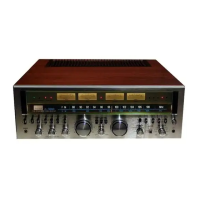
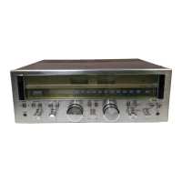
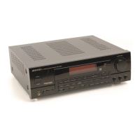
| Model | RZ-5100AV |
| Category | Stereo Receiver |
| Language | English |