EasyManua.ls Logo

Sansui RZ-1500 Service Manual

Sansui RZ-1500
18 pages
To Next Page IconTo Next Page
Page #1 background imageLoading...
Page #1 background image
ST
SANSUI
RZIS00O—
COMPUTERIZED
STEREO
RECEIVER
CAUTION
|
|
SERVICE
MANUAL!
NOTICE
For
servicing
RZ-1500,
please
refer
to
service
manual
for
the
RZ-1000
with
this
manual,
since
most
of
the
parts
and
circuits
employed
in
RZ-1500
are
in
common
with
the
RZ-1000.
On
the
parts
list,
the
changed
parts
are
specified
by
"®"
mark
on
top
of
the
Stock
No.
,
1.
Parts
identified
by
the
A
symbol
on
the
schematic
diagram
and
the
parts
list
are
critical
for
safety.
Use
only
replacement
parts
that
have
critical
characteristics
recommended
by
the
manufacturer.
2.
Make
leakage-current
or
resistance
measurements
to
determine
that
exposed
parts
are
acceptably
insulated
from
the
supply
circuit
before
returning
the
appliance
to
the
customer.
SPECIFICATIONS
Audio
section
Power
output
Min,
RMS,
both
channels
driven,
from
40
to
20,000
Fz
with
no
more
than
0.09%
total
harmonic
distortion
32
watts
per
channel
into
8
ohms
DIN
38
watts
per
channel
into
8
ohms.
Total
harmonic
distortion
less
than
0.09%
at
or
below
rated
min.
RMS
power
output
Load
impedance.............
4~16
ohms
Input
sensitivity
and
impedance
(1
kHz)
PHONO
i
csisccazssaseseseces
2.5
mV/47 kohms
Di
teen
clases
.
200
mV/47
kohms
TAPE PLAY
150.mV/47
kohms
Frequency
response
(at
|
watt)
seusvesbvonvsnqwencsnanesengonnees
10
to
70,000
Hz,
+1
dB,
—3
dB
Signal
to
noise
ratio
(short-circuit,
A-network)
PHONO
iscsapusnseatsrsedes
73
dB
CD,
TAPE
PLAY...
90
dB
Controls
BASS
vvevvonedneunssvesesvonens
+8
dB
at
50
Hz
TREBLE
cvsscsnsscngysenvnaves
+7
dB
at
10
kHz
LOUDNESS
cassssssvessuxcs
+10
dB
at
50
Hz
Sa
aaieaactntecete
+6
dB
at
10
kHz
(VOLUME:
—30
dB
position)
FM
section
Tuning
range...
cee
88
to
108
Mt
iz
Usable
sensitivity
Mono
JHE
oo...
13.2
dBf
(2.5
pV:
T-100)
50
dB
quicting
sensitivity
SECPES
cciccs
conrwaticessiiuense
40
dBf
Signal
to
noise
ratio
(at
65
dBA
SLORCO.
scxcqceceyeasapaxounsies
70
dB
Distortion
(at
65
d8Bf
SlereO
scseccanaassesadececisss
less
than
0.3%
at
1,000
Hz
Stereo
separation
............
40
dB
at
1,000
Fz
AM
section
Tuning
range...
530.to
1,600
kidz
Usable
sensitivity
(Loop
antenna)
.
Sidi
rak
caveasee
see
G
tn
tne
55
dB/m
(562
pV/m)
Signal
to
noise
ratio........
40
dB
Others
:
Power
requirements........
120/220/240V
50/60
Hz
For
U.S.A.
and
Canada
120V
(60
Hz)
Power
consumption
........
180
watts
220
VA
Rated
280
walts
Maximum
Dimensions
.................
430
mm
(16-15/16")
W
125
mm
(4-15/167)
FH
335
mm
(13-1/47)
D
Weight
ccsicccsessscscavcesreacsene
6.6
kg
(14.6
Ibs)
net
7.9
kg
(17.4
Ibs)
packed
*
Design
and
specifications
subject
to-changest
withoul
notice
far
ime
provements.
*
Due
to
local
laws
and
regulations,
this
unit
sald
in
seme
areas
is
not
equipped
with
variable
voltage
selector.
Question and Answer IconNeed help?

Do you have a question about the Sansui RZ-1500 and is the answer not in the manual?

Sansui RZ-1500 Specifications

General IconGeneral
BrandSansui
ModelRZ-1500
CategoryStereo Receiver
LanguageEnglish

Summary

CAUTION

Safety Precautions for Servicing

Critical parts and insulation measurements for safe operation.

SPECIFICATIONS

Audio Section Specifications

Details on power output, distortion, sensitivity, and frequency response.

FM Section Specifications

Tuning range, sensitivity, signal-to-noise ratio, and distortion for FM.

AM Section Specifications

Tuning range, sensitivity, and signal-to-noise ratio for AM.

General Unit Specifications

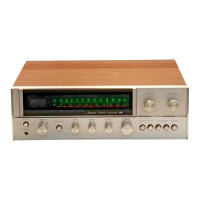
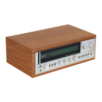
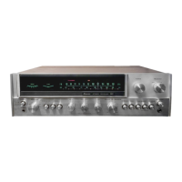
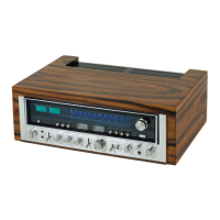
Power requirements, dimensions, and weight of the stereo receiver.

NOTICE AND LISTS

Service Manual Usage Guidance

Instructions on using this manual with the RZ-1000 manual and parts list symbols.

Product Packing and Accessory Lists

Lists of packaging contents and supplied accessories.

PARTS LIST OF BOARD

F-6001 Main Board Component List

Detailed list of parts for the F-6001 main circuit board.

INTERIOR BLOCK DIAGRAM & TERMINAL FUNCTION OF IC

LA1266 IC Terminal Functions

Terminal details for the LA1266 IC used in FM/AM IF stages.

LA3410 IC Terminal Functions

Terminal details for the LA3410 IC used for MPX functions.

M5218L/M5218P IC Terminal Functions

Terminal details for the M5218L/M5218P Operational Amplifier ICs.

BLOCK DIAGRAM AND ADJUSTMENT

Overall System Block Diagram

Visual representation of the RZ-1500's functional blocks.

Power Amplifier Bias Adjustment

Procedure for adjusting bias current in the power amplifier stage.

FM Tuner Adjustment Procedures

Steps for adjusting FM IF coil, reference frequency, and technical hints.

AM ADJUSTMENT

AM IF and Tuning Adjustment

Steps for adjusting AM IF coil and tuning circuit.

DISPLAY PATTERN AND PIN ASSIGNMENT

CP3023 FL Display Pattern

Visual layout of characters and segments on the FL display.

CP3023 FL Display Pin Assignment

Mapping of pins to display segments and functions.

PARTS LOCATION ON BOARD

F-6001 Main Board Component Placement

Diagram showing the physical location of components on the main board.

PARTS LOCATION ON OTHER BOARDS

Component Placement on Various Boards

Diagrams showing component locations for tuner, speaker, master/tone, and power amp boards.

CIRCUIT SCHEMATICS AND IC FUNCTIONS

Overall Circuit Schematic Diagram

Comprehensive electrical schematic of the RZ-1500 unit.

LC7218 PLL Synthesizer Terminal Details

Terminal pinout and function description for the LC7218 PLL synthesizer.

TC9163N Analog Switch Terminal Details

Terminal pinout and function description for the TC9163N analog switch.

IC TERMINAL FUNCTIONS

TMP47C870N Control IC Terminal Details

Terminal pinout and function description for the TMP47C870N control IC.
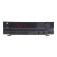
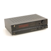
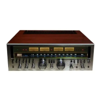
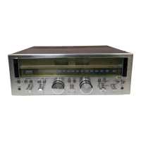
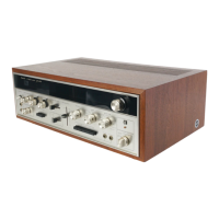
Related product manuals