Page 8
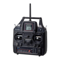
Antenna: Transmits the signal from the transmitter to the receiver in the model.
Never touch the transmitter antenna during use. Doing so may cause loss of transmitter output, resulting in loss of signal.
should be held so that the antenna is vertical at all times.
Antenna Reception Wire: The portion of the antenna that receives the transmitter signal.
The Antenna Reception Wire should never be bent or it could be damaged and limit the range of your model.
Battery Compartment: Houses the 4 'AA' Alkaline cells that power the transmitter.
Bind Button and Bind LED: Used in the process of Binding the transmitter and receiver.
Charging Jack: Used for onboard charging of the optional 6 cell 1500mAh Ni-MH battery.
Do not attempt to charge Alkaline batteries. Only the recommended SANWA 100v〜240v AC charger should be used through
the Charging Jack. If using an after-market Peak charger or other type of fast charger, the battery should be removed from
the transmitter to avoid damage to the transmitter circuitry.
Coaxial Cable: The portion of the antenna that extends the Antenna Reception Wire. The Coaxial Cable can be bent into gentle
curves, however, do not bend the Coaxial Cable acutely, or repeatedly bend it, or the antenna core can be damaged. The Coaxial
Cable should be installed through a nylon tube (antenna tube) in the vertical position for the best reception.
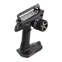
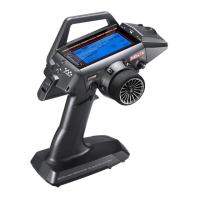
Grip: The Grip is molded in an ergonomic shape for increased comfort, control and feel.
LCD: The heart of the programming and display features of the transmitter. All programming and transmitter display functions
are shown on the LCD.
Power Indicator Light: Flashes slowly when the transmitter is turned ON and transmitting a signal. Flashes in rapid succession
indicating that Mixing is Active. The Power Indicator Light is also used during the Binding process.
Power Switch: Turns the transmitter ON and OFF.
Steering Wheel: Proportionally operates the model's right and left steering control. The Steering Wheel features a foam grip for
increased comfort, control and feel.
Throttle Trigger: Controls the speed of the model, both forward and backward, or the model's brake. The Throttle
Trigger neutral
position can be adjusted to best suit your driving style.
Throttle Trim Switch: Used to adjust the center trim of the throttle servo.
Steering Trim Switch: Used to adjust the center trim of the steering servo.
Programmable Trim Switch: The TRM Switch controls different options, depending on your programming preferences. In the
EPA, Throttle Brake EPA, Auxiliary Channel 3 High EPA, Auxiliary Channel 3 Low EPA, and more.
Programming Keys: The Programming Keys are used to facilitate transmitter programming. The four Programming Keys
consist of two MENU Keys (Right and Left), one YES/+ (Increase) Key, and one NO/- (Decrease) Key.
Auxiliary Lever (Channel 3): The Auxiliary Lever controls different options, depending on your programming preferences. In
control the different Mixes that are available.
Throttle Trigger Adjustment Screw: Used to adjust the neutral position of the Throttle Trigger.
Throttle Trigger Adjustment Lock Screw: Used to lock the Throttle Trigger neutral position.
Throttle Trigger Adjustment Indicator: Indicates the current neutral position of the Throttle Trigger. As the neutral position is
adjusted forward or backward, the Adjustment Indicator will move forward or backward. The molded hash mark indicates the
default factory neutral position.
Wrist Strap Anchor: Used to connect the optional wrist strap (available separately) to the transmitter.
FEATURES FAMILIARIZATION
FEATURES DESCRIPTIONS
The antenna is flexible for extra safety. Do not bend or twist the antenna or damage could result. During use, the transmitter
default configurations, the TRM Switch controls the steering Dual Rate adjustment. The TRM Switch can also control Throttle High
the default configuration, the Auxiliary Lever controls Auxiliary Channel 3. In addition, the Auxiliary Lever is used to program and