Do you have a question about the Sanyo C4272R and is the answer not in the manual?
| Brand | Sanyo |
|---|---|
| Model | C4272R |
| Category | Air Conditioner |
| Language | English |
Detailed specifications for various indoor and outdoor unit models, including performance, electrical ratings, and features.
Lists major internal components for indoor units, such as fan motors, coils, and safety devices.
Details major components for outdoor units, including compressors, fans, and heat exchangers.
Specifies other indoor unit components like transformers, thermistors, drain pumps, and float switches.
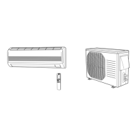
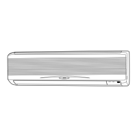
Provides installation diagrams and measurements for various indoor unit types, including clearances.
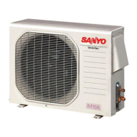
Presents installation diagrams and measurements for outdoor units, including required spaces.
Illustrates refrigerant flow paths and specifies operating temperature ranges for cooling and heating.
Details heating capacity ratios and presents noise criterion curves for different unit types.
Covers tubing length, installation instructions, electrical wiring requirements, and precautions.
Instructions for setting up the wireless remote controller and configuring the indoor unit control PCB for wireless operation.
Explains the thermostat-controlled compressor operation for maintaining room temperature in cooling and heating.
Details the cold draft prevention function and automatic indoor fan speed adjustments for optimal comfort.
Outlines system controls for discharge temperature, current release, freeze prevention, and short-cycle prevention.
Identifies components on the outdoor unit control PCB and explains their functions and settings.
Contains electrical wiring and schematic diagrams for various indoor unit types, detailing component connections.
Provides electrical wiring and schematic diagrams for different outdoor unit models, showing component interconnections.
Explains meaning of alarm codes, display indicators, and potential causes of system malfunctions.
Correlates alarm symptoms with judgment conditions and provides guidance on parts inspection and correction.
Step-by-step troubleshooting flowcharts for specific alarms, aiding in diagnosing faults.
Provides resistance values for temperature sensors at different temperatures, essential for sensor testing.
Introduces the remote tool for EEPROM settings, monitoring alarms, and checking unit status.
Guides on using the remote controller for normal display operations, unit status, and temperature monitoring.
Instructions for viewing outdoor unit alarm history and modifying EEPROM settings via the maintenance remote control.
Covers essential checks before test runs, safety precautions, and customer interaction guidelines.
Step-by-step guide for initiating and managing test runs using the remote controller and automatic address setting.
Table of self-diagnostic functions, corrections, and examples of basic wiring diagrams for system setup.