4 - 13
PCB and Functions
2. Indoor Unit Control PCB
1
2
3
4
5
6
7
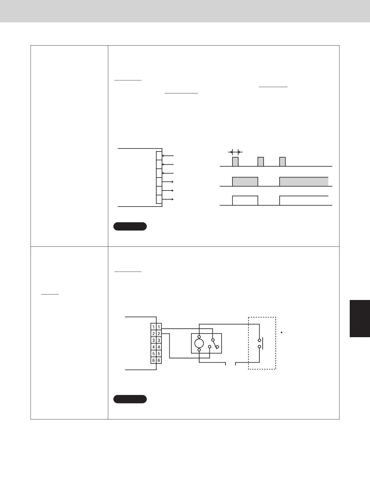
2-7. Explanation of Functions
T10
(CN061)
(Remote control operation)
6P plug (yellow): Used for remote control.
Control items:
①
Start/stop input
②
Remote controller prohibit input
③
Start signal output
④
Alarm signal output
(Condition)
①
1-2 (Pulse input): Unit ON/OFF condition switching with a pulse signal.
(1 pulse signal: shortage status more than 300msec.or more)
②
2-3 (Static input): Open/ Operation with Remote is permitted.(Normal condition)
Close/ Remote controller is prohibited.
③
4-5 (Static output): 12V output during the unit ON. / No output at OFF
④
5-6(Static output): 12V output when some errors occur / No output at normal
Example of signal
1
2
3
4
5
6
COM
COM
T10
(yellow)
+12V
300msec.
or more
+12
ON ONOFFUnit condition
4-5 (output)
1-2 (pulse input)
NOTE
The wire length from indoor unit to the Relay must be within 6.5ft.
Pulse signal changeable to static with JP cutting. (Refer to JP001)
z
T10*
(CN061)
Forced OFF control
* Need to set EEPROM
data at Code “2E” to
“0001” (Refer to Page
2-35/ Detailed Setting
Function)
This is a method to control the indoor unit individually.
(Condition)
1-2 (Static input): Close/ Operation with Remote is permitted. (Normal condition)
Open/ Unit is forcibly OFF and Remote controller operation is prohibited.
Example of wiring
Relay
(Field supply)
The contact in the
figure is a state
where the card is
pulled out.
POWER
External contact
(Card switch box, etc.:
field supply)
Indoor unit
control PCB
T10
(YEL)
NOTE
The wire length from indoor unit to the Relay must be within 6.5ft.
Special-order parts: Wire K 623 176 6814
z
z
SM830183-003WAYECO-i.indb13SM830183-003WAYECO-i.indb13 2010/03/0311:15:182010/03/0311:15:18