2 - 39
Remote Control Functions
3. Timer Remote Controller
1
2
3
4
5
6
7
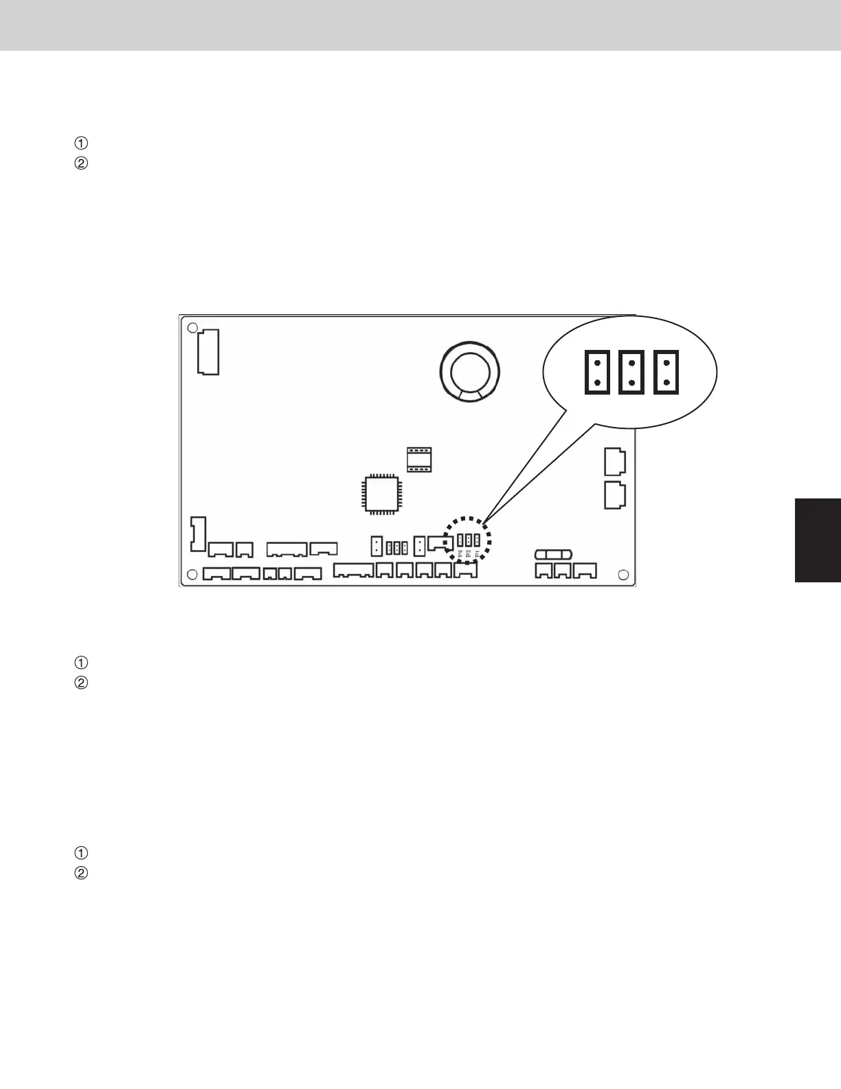
Selecting the DC fan motor tap (when setting from the PCB)
●
4-way Air Discharge Semi-Concealed type
<Procedure> Stop the system before performing these steps.
Open the electrical component box cover, then check the indoor unit control PCB.
Connect the jumper connector (2P: yellow) which was supplied with the accessory to the correct connector pin
on the indoor unit control PCB according to the setting number which was confirmed in Table 1 (Table of DC
Fan Motor Tap Settings).
•
If the setting No. is (1), then connect the jumper connector to the connector pin TP1 (2P: red) on the indoor unit
control PCB.
•
If the setting No. is (3), then connect the jumper connector to the connector pin TP3 (2P: yellow) on the indoor unit
control PCB.
●
Suspended type
<Procedure> Stop the system before performing these steps.
Open the electrical component box cover, then check the indoor unit control PCB.
Connect the jumper connector (2P: yellow) which was supplied with the accessory to the correct connector pin
on the indoor unit control PCB according to the setting number which was confirmed in Table 2 (Table of DC
Fan Motor Tap Settings).
•
If the setting No. is (1), then connect the jumper connector to the connector pin TP1 (2P: red) on the indoor unit
control PCB.
•
If the setting No. is (3), then connect the jumper connector to the connector pin TP3 (2P: yellow) on the indoor unit
control PCB.
●
1-way Air Discharge Semi-Concealed type
<Procedure> Stop the system before performing these steps.
Open the electrical component box cover, then check the indoor unit control PCB.
Connect the jumper connector (2P: yellow) which was supplied with the accessory to the correct connector pin
on the indoor unit control PCB according to the setting number which was confirmed in Table 3 (Table of DC
Fan Motor Tap Settings).
•
If the setting No. is (1), then connect the jumper connector to the connector pin TP1 (2P: red) on the indoor unit
control PCB.
•
If the setting No. is (3), then connect the jumper connector to the connector pin TP3 (2P: yellow) on the indoor unit
control PCB.
TP6
White Yellow
Red
TP3 TP1
SM830183-003WAYECO-i.indb39SM830183-003WAYECO-i.indb39 2010/03/0311:14:482010/03/0311:14:48