EasyManua.ls Logo

Sanyo CLM1972 User Manual

Sanyo CLM1972
103 pages
To Next Page IconTo Next Page
Page #1 background imageLoading...
Page #1 background image
IMPORTANT
These air conditioners employ new
refrigerant R410A.
Pay special attention when
servicing the unit.
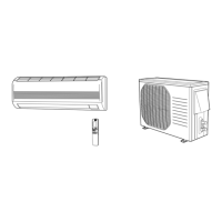
Wall mounted type
KMS0772
KMS0972
KMS1272
KMS1872
KMS2472
< Applicable Indoor Units >
TECHNICAL & SERVICE MANUAL
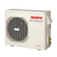
OUTDOOR UNIT : CLM1972
CLM2472
CLM3172
DC INVERTER MULTI-SYSTEM AIR CONDITIONER
Destination: North America
Product Code No.
1 852 330 33
1 852 330 34
1 852 330 35
REFERENCE NO.
SM700680-03
Capacity at 230V
19,700 BTU/h
25,400 BTU/h
30,600 BTU/h
Outdoor Model No.
CLM1972
CLM2472
CLM3172
NOTE
CLM1972
CLM2472
CLM3172
For details about the combination, refer to
"Unit Combination Table" in the Appendix
of this manual.
FILE NO.
Other manuals for Sanyo CLM1972

Questions and Answers:

Sanyo CLM1972 Specifications

General IconGeneral
Cooling Capacity18000 BTU/h
Heating Capacity19000 BTU/h
Weight (Indoor Unit)12 kg
Noise Level (Outdoor)52 dB
Power Supply220-240V, 50Hz

Summary

Safety and Precautions

Please Read Before Starting

Essential safety and operating guidelines for installers/service personnel.

Special Precautions

Detailed safety measures covering wiring, transport, installation, etc.

Applicable Indoor Units

Indoor Unit Combinations

Table showing compatible indoor units for outdoor models.

Operating Range

Cooling Operating Temperatures

Specifies temperature limits for cooling operation.

Unit Specifications

CLM1972 Specifications (230V)

Detailed specs for CLM1972 outdoor unit (230V).

Unit Specifications (CLM1972, 208V)

CLM1972 Specifications (208V)

Detailed specs for CLM1972 outdoor unit (208V).

Unit Specifications (CLM2472)

CLM2472 Specifications (230V)

Detailed specs for CLM2472 outdoor unit (230V).

Unit Specifications (CLM2472, 208V)

CLM2472 Specifications (208V)

Detailed specs for CLM2472 outdoor unit (208V).

Unit Specifications (CLM3172)

CLM3172 Specifications (230V)

Detailed specs for CLM3172 outdoor unit (230V).

Unit Specifications (CLM3172, 208V)

CLM3172 Specifications (208V)

Detailed specs for CLM3172 outdoor unit (208V).

Major Component Specifications

CLM1972 Major Components

Specs for control PCB, compressor, fan motor, heat exchanger.

Major Component Specifications (CLM2472)

CLM2472 Major Components

Specs for control PCB, compressor, fan motor, heat exchanger.

Major Component Specifications (CLM3172)

CLM3172 Major Components

Specs for control PCB, compressor, fan motor, heat exchanger.

Other Component Specifications

Sensor Specifications

Details on temperature and other sensors used in the units.

Dimensional Data

CLM1972 Outdoor Unit Dimensions

Drawings and dimensions for CLM1972 outdoor unit.

Dimensional Data (CLM2472)

CLM2472 Outdoor Unit Dimensions

Drawings and dimensions for CLM2472 outdoor unit.

Dimensional Data (CLM3172)

CLM3172 Outdoor Unit Dimensions

Drawings and dimensions for CLM3172 outdoor unit.

Refrigerant Flow Diagram

CLM1972 Refrigerant Flow

Diagram illustrating refrigerant path for CLM1972.

Refrigerant Flow Diagram (CLM2472)

CLM2472 Refrigerant Flow

Diagram illustrating refrigerant path for CLM2472.

Refrigerant Flow Diagram (CLM3172)

CLM3172 Refrigerant Flow

Diagram illustrating refrigerant path for CLM3172.

Performance Data

CLM1972 Temperature Charts

Performance charts for CLM1972 with KMS0772.

Performance Data (CLM1972 / KMS0972)

CLM1972 Temperature Charts (KMS0972)

Performance charts for CLM1972 with KMS0972.

Performance Data (CLM1972 / KMS1272)

CLM1972 Temperature Charts (KMS1272)

Performance charts for CLM1972 with KMS1272.

Performance Data (CLM1972 / KMS1872)

CLM1972 Temperature Charts (KMS1872)

Performance charts for CLM1972 with KMS1872.

Performance Data (CLM2472)

CLM2472 Temperature Charts (KMS0772)

Performance charts for CLM2472 with KMS0772.

Performance Data (CLM2472 / KMS0972)

CLM2472 Temperature Charts (KMS0972)

Performance charts for CLM2472 with KMS0972.

Performance Data (CLM2472 / KMS1272)

CLM2472 Temperature Charts (KMS1272)

Performance charts for CLM2472 with KMS1272.

Performance Data (CLM2472 / KMS1872)

CLM2472 Temperature Charts (KMS1872)

Performance charts for CLM2472 with KMS1872.

Performance Data (CLM2472 / KMS2472)

CLM2472 Temperature Charts (KMS2472)

Performance charts for CLM2472 with KMS2472.

Performance Data (CLM3172 / KMS0772)

CLM3172 Temperature Charts (KMS0772)

Performance charts for CLM3172 with KMS0772.

Performance Data (CLM3172 / KMS0972)

CLM3172 Temperature Charts (KMS0972)

Performance charts for CLM3172 with KMS0972.

Performance Data (CLM3172 / KMS1272)

CLM3172 Temperature Charts (KMS1272)

Performance charts for CLM3172 with KMS1272.

Performance Data (CLM3172 / KMS1872)

CLM3172 Temperature Charts (KMS1872)

Performance charts for CLM3172 with KMS1872.

Performance Data (CLM3172 / KMS2472)

CLM3172 Temperature Charts (KMS2472)

Performance charts for CLM3172 with KMS2472.

Cooling Capacity

CLM1972 Cooling Capacity

Cooling capacity data for CLM1972 with KMS0972 x 3.

Cooling Capacity (CLM2472)

CLM2472 Cooling Capacity

Cooling capacity data for CLM2472 with KMS0972 x 3.

Cooling Capacity (CLM3172)

CLM3172 Cooling Capacity

Cooling capacity data for CLM3172 with KMS0972 x 4.

Cooling Capacity (Low Ambient)

CLM1972 Low Ambient Cooling Capacity

Cooling capacity data at low ambient temps.

Cooling Capacity (Low Ambient, CLM2472)

CLM2472 Low Ambient Cooling Capacity

Cooling capacity at low ambient temps for CLM2472.

Cooling Capacity (Low Ambient, CLM3172)

CLM3172 Low Ambient Cooling Capacity

Cooling capacity at low ambient temps for CLM3172.

Electrical Data

CLM1972 Electric Wiring Diagram

Wiring schematic for CLM1972 outdoor unit.

Electric Wiring Diagrams (CLM2472)

CLM2472 Electric Wiring Diagram

Wiring schematic for CLM2472 outdoor unit.

Electric Wiring Diagrams (CLM3172)

CLM3172 Electric Wiring Diagram

Wiring schematic for CLM3172 outdoor unit.

Functions

Explanation of Operations

Explanation of unit controls and operational modes.

Functions (Continued)

COOL Mode and Freeze Prevention

Details on COOL mode, thermostat behavior, and freeze protection.

Functions (SENSOR DRY)

SENSOR DRY Mode Operation

Explanation of SENSOR DRY operation and fan modes.

Protective Functions

Low Ambient Cooling Operation

Describes how the unit operates in low ambient temperatures.

Protective Functions (Current Control)

Automatic Frequency Control

How frequency adjusts to manage operating current.

Protective Functions (Cont.)

Compressor Temperature Control

Frequency control based on compressor discharge temperature.

Troubleshooting

Inspection and Repair Precautions

Safety warnings for inspecting electronic circuits.

Troubleshooting (Error Lamps)

Error Monitor Lamp Display

Interpreting error codes from monitor lamps.

Troubleshooting (Outdoor System)

Checking the Outdoor Unit

Procedures for checking outdoor unit operation.

Troubleshooting (Part Diagnosis)

Problems and Inspection Points

Table mapping problems to inspection points for each part.

Troubleshooting (Part Details)

Inspection Points for Each Part

Detailed checks for specific components like fuses, compressor.

Troubleshooting (Expansion Valve)

Electric Expansion Valve Checks

Procedures for checking and replacing the electric expansion valve.

Troubleshooting (Sensors, Breaker, Refrigerant)

Branch Tubing Sensor, Breaker, and Refrigerant Pressure Checks

Checks for sensors, breaker, and refrigerant pressure issues.

Troubleshooting (Fan Motor)

Fan Motor Diagnosis and Remedy

Steps to diagnose and fix fan motor issues.

Refrigerant R410A Precautions

Characteristics of R410A

Properties, composition, and characteristics of R410A refrigerant.

Refrigerant Handling and Servicing

Pre-Servicing Checklist

Checks and precautions before servicing R410A systems.

Refrigerant Tools and Procedures

Tools Specifically for R410A

List of specialized tools required for R410A.

Tubing Installation Procedures

Guidelines for installing refrigerant tubing correctly.

Refrigerant Procedures (Compressor)

Compressor Replacement Procedure

Steps for replacing a malfunctioning compressor.

Refrigerant Procedures (Recharging)

Recharging Refrigerant

Method for charging refrigerant in liquid state.

Refrigerant Handling (Leaks)

Procedure for Refrigerant Leaks

Steps for detecting, repairing, and recharging after leaks.

Refrigerant Handling (Retrofit)

Charging Additional Refrigerant

Guidelines for adding refrigerant when tubes are extended.

Retro-Fitting Existing Systems

Advice on using existing units/tubing with R410A.

Appendix A: Installation Instructions

Installation Procedures Overview

Lists the main sections of the installation guide.

Installation Instructions Overview

Model Combinations

Lists compatible indoor and outdoor unit combinations.

General Installation Information

Required Installation Tools

List of tools needed for installation (not supplied).

Supplied Accessories

List of accessories included with the unit.

Optional Copper Tubing Kit

Information on optional kits for tubing and insulation.

Copper Tube and Insulation Material

Details on copper tube types and insulation requirements.

Installation Site Selection

Indoor Unit Installation Site

Guidelines for selecting a proper location for the indoor unit.

Connecting Indoor Units

Connecting Indoor Units for CLM1972/CLM1972

Diagrams and instructions for connecting indoor units to CLM1972.

Connecting Indoor Units (CLM2472)

Connecting Indoor Units for CLM2472/CLM2472

Diagrams for connecting indoor units to CLM2472.

Connecting Indoor Units (CLM3172)

Connecting Indoor Units for CM3172/CLM3172

Diagrams for connecting indoor units to CLM3172.

Connecting Indoor Units (CLM3172, Cont.)

Connecting Indoor Units for CLM3172/CLM2472

Diagrams for connecting indoor units to CLM3172/CLM2472.

Outdoor Unit Installation

Outdoor Unit Placement Guidelines

Rules for selecting an outdoor unit location (avoid/do).

Baffle Plates for Outdoor Unit

Instructions for installing baffle plates on CLM models.

Baffle Plate Details

Recommended Baffle Plate Dimensions

Dimensions and parts for air intake/discharge baffles.

Baffle Plate Installation

Installation Procedure for Baffle Plates

Step-by-step guide for installing baffle plates.

Outdoor Unit Dimensions

Outer Dimensions of CLM1972/CLM2472/CLM3172

Drawings showing outer dimensions for all models.

Outdoor Unit Installation Diagram

Diagram of Outdoor Unit Installation

Shows required spacing and connections for installation.

Installation Process

Embedding Tubing and Wiring

Instructions for routing and securing tubing and wires.

Use of the Flaring Method

Explanation of the flaring technique for tube connections.

Flaring Procedure with Flare Tool

Step-by-step guide for creating flares on tubing.

Connecting Refrigerant Tubes

Caution Before Tightening Tubes

Precautions for connecting tubes to prevent leaks.

Tubing Connections and Torque

Steps and torque specifications for tubing connections.

Finishing Tube Installation

Insulation of Refrigerant Tubing

Requirements for insulating refrigerant tubing.

Taping the Tubes

Instructions for taping tubing bundles together.

Finishing the Installation

Sealing wall holes after installation.

Air Purging

Air Purging with Vacuum Pump

Procedure for purging air from the system using a vacuum pump.

Air Purging Details

Vacuum Pump Operation and Leak Testing

Steps for operating the vacuum pump and checking for leaks.

Pump Down Procedure

What is Pump-Down?

Explanation of pump-down and its purpose.

Pump-Down Procedure

Step-by-step guide for performing pump-down.

Wiring Instructions

General Wiring Precautions

Safety and general guidelines for wiring.

Recommended Wire Length and Diameter

Table for wire sizing based on length.

Wiring System Diagrams

Wiring Diagrams for Unit Configurations

Schematics for 3-unit and 4-unit systems.

Connecting Wiring to Terminals

Terminal Connection Procedures

Step-by-step guide for connecting wires to terminals.

Outdoor Unit Wiring

Wiring Instructions for Outdoor Unit Connections

Specifics on connecting outdoor unit and inter-unit cables.

Test Run and Checks

Performing the Test Run

Procedures for conducting a test run.

Checking Tubing and Wiring

Verifying connections and operation after test run.

Final Installation Steps

Home Automation Device Connection

How to connect a HA device to the indoor unit.

Installation Check Sheet

Checklist to ensure proper installation.

Appendix B: Unit Combination Tables

List of Combination Tables

Index of tables showing unit compatibility.

Unit Combination Tables (CLM1972)

CLM1972 Combinations (3-Room)

Details on indoor unit combinations for CLM1972 (3-room).

Unit Combination Tables (CLM1972, 230V)

CLM1972 Combinations (230V)

Table showing operatable indoor units for CLM1972 at 230V.

Unit Combination Tables (CLM1972, 208V)

CLM1972 Combinations (208V)

Table showing operatable indoor units for CLM1972 at 208V.

Unit Combination Tables (CLM2472)

CLM2472 Combinations (4-Room)

Details on indoor unit combinations for CLM2472 (4-room).

Unit Combination Tables (CLM2472, 230V)

CLM2472 Combinations (230V)

Table showing operatable indoor units for CLM2472 at 230V.

Unit Combination Tables (CLM2472, 208V)

CLM2472 Combinations (208V)

Table showing operatable indoor units for CLM2472 at 208V.

Unit Combination Tables (CLM3172)

CLM3172 Combinations (4-Room)

Details on indoor unit combinations for CLM3172 (4-room).

Unit Combination Tables (CLM3172, 230V)

CLM3172 Combinations (230V)

Table showing operatable indoor units for CLM3172 at 230V.

Unit Combination Tables (CLM3172, 208V)

CLM3172 Combinations (208V)

Table showing operatable indoor units for CLM3172 at 208V.

Related product manuals