TAPE ADJUSTMENTS
Adjustment Item
I
Test Tape
I
Measuring
Instrument
(a) HEAD AZIMUTH
VT1738 etc. AC+oltmeter
DECK “A” (1OKHZ)
(b) HEAD AZIMUTH
I
vl1738 etc.
I
AC-voltmeter
DECK “B” (l OKHz)
(c) MOTOR SPEED
I
MlT-l 11 FREQUENCY
(NORMAL)
(3,000Hz) COUNTER
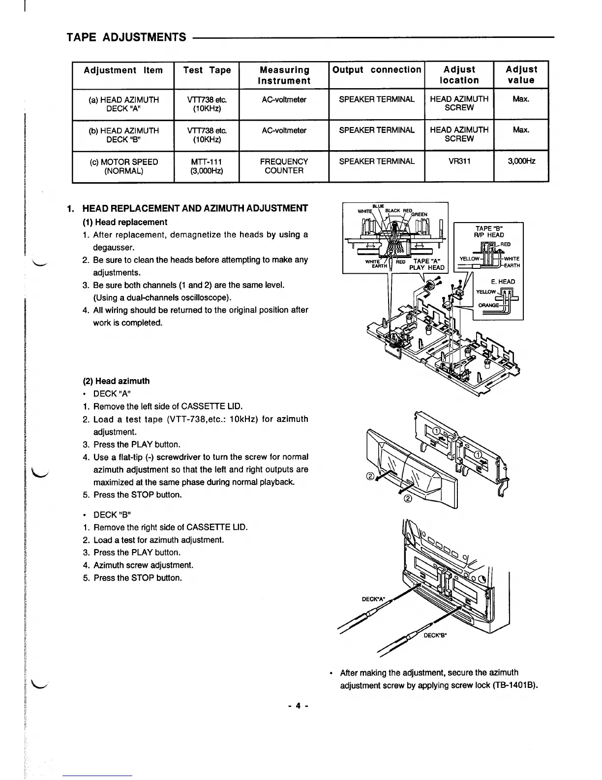
1. HEAD REPLACEMENT AND AZIMUTH ADJUSTMENT
(1) Head replacement
1.
After replacement, demagnetize the heads by using a
degausser.
2. Be sure to clean the heads before attempting to make any
adjustments.
3. Be sure both channels (1 and 2) are the same level.
L
L
(Using a dual-channels oscilloscope).
4.
All wiring should be returned to the original position after
work is completed.
(2)
Head azimuth
. DECK IIW
1.
Remove the left side of CASSETTE LID.
2. Load a test tape (VTT-738,etc.: 10kHz) for azimuth
adjustment.
3. Press the PLAY button.
4. Use a flat-tip (-) screwdriver to turn the screw for normal
azimuth adjustment so that the left and right outputs are
maximized at the same phase during normal playback.
5. Press the STOP
button.
● DECK “B”
1. Remove the right side of CASSEITE LID.
2. Load a test for azimuth adjustment.
3. Press the PLAY button.
4. Azimuth screw adjustment.
5. Press the STOP button.
Output connection
Adjust
Adjust
location value
SPEAKER TERMINAL
HEAD AZIMUTH
I
Max.
SCREW
SPEAKER TERMINAL
HEAD AZIMUTH
I
Max.
SCREW
SPEAKER TERMINAL
VR311
3,000Hz
‘5
TAPE “B”
IUP HEAD
S
RED
YELLOW
WHITE
EARTH
.
After making the adjustment, secure the azimuth
adjustment screw by applying screw lock (TB-1401 B).
-4-
 Loading...