EasyManua.ls Logo

Sanyo DC-C70 - User Manual

Sanyo DC-C70
39 pages
To Next Page IconTo Next Page
Loading...
IFILE NO.
I
Service Manual
Mini Component System
DC-C70 (AU)
Contents
Specifications ................................................................... 1
Laser beam safety precaution .......................................... 1
What to do if .....................................................................2
CD pick-up maintenance ..................................................2
Service mode ................................................................... 2
CD player adjustments .....................................................3
Tape adjustments ............................................................4
Tuner adjustments ...........................................................6
Exploded view
(Cabinet & Chassis) ...................................................... 7
(Tape mechanism) ........................................................ 15
(CD changer mechanism) ............................................. 17
(CD base mechanism) .................................................. 18
Parts list
(Cabinet & Chassis) ...................................................... 8
(Tape mechanism) ........................................................ 16
(CD mechanism) ........................................................... 18
t ‘?
1
LI
1
.—— ——— ——— ——— ——— ——— —.
PRODUCT CODE No.
12956005
IC block diagram & description ........................................ 19
FL display description ......................................................24
IC & Transistor voltages ................................................... 25
Schematic diagram
(CD) ...............................................................................26
(DECK) ..........................................................................30
(FRONT) ....................................................................... 32
(TUNER) ....................................................................... 36
(AMPLIFIER) ................................................................. 40
Wiring diagram
(CD) ...............................................................................28
(DECK) .......................................................................... 29
(FRONT)
....................................................................... 34
(TUNER & AMPLIFIER) ................................................ 38
(POWER TRANSFORMER) ........................................ 42
(POWER SWITCH, DISC SWITCH and e.t.c.) ...........43
Wiring connection ............................................................ 44
.—— ——— ——— —-
This service manual consists of “DC-C70U” (Main unit :129559 05), “RB-C30AR” (Remote control),
“SX-C70L” (Speaker system: 133697 02) and “SX-C70R” (Speaker system: 133 69802).
“L
REFERENCE No. SM5810048
Question and Answer IconNeed help?

Do you have a question about the Sanyo DC-C70 and is the answer not in the manual?

Sanyo DC-C70 Specifications

General IconGeneral
Power output20 watts per channel into 8Ω (stereo)
Frequency response20Hz to 20kHz
Total harmonic distortion0.8%
Dimensions440 x 146 x 305mm
Weight7.5kg
Input sensitivity2.5mV (MM), 150mV (line)

Summary

System Specifications

Tuner, Cassette, and CD Changer Specs

Technical details for tuner, cassette, and CD changer functions.

General and Speaker System Specs

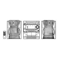
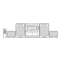
Overall system specs and speaker system details.

Laser Beam Safety Precautions

Troubleshooting and Maintenance

Troubleshooting: Unit Not Normal

Steps for resetting the unit when operation is abnormal.

CD Pickup Lens Maintenance

Procedure for cleaning the CD pickup lens.

Service Mode Operations

Service Mode: CD Repair

Procedure for entering CD repair mode and error codes.

Service Mode: FL Connection Check

Procedure for checking FL display and LED connections.

CD Player Adjustments

CD Player Adjustment: Tracking Balance

Procedure for confirming tracking balance using an oscilloscope.

CD Player Adjustment: Eye Pattern Check

Procedure for checking the "eye" pattern with an oscilloscope.

Tape Mechanism Adjustments

Tape Adjustment: Head Azimuth

Procedures for adjusting head azimuth on both decks.

Tape Adjustment: Motor Speed and Torque

Procedures for motor speed calibration and mechanism torque checks.

Tuner Adjustments

Tuner Adjustment: FM Section

Procedures for FM tuning and tracking adjustments.

Tuner Adjustment: AM Section

Procedures for AM tuning and tracking adjustments.

Exploded View: Cabinet and Chassis

Parts List

Chassis, Cabinet, and Fixing Parts

Lists for chassis, cabinet, and fastener components.

Packing and Accessory Parts

List of packing and accessory components.

Product Safety Notice

Exploded View: Tape Mechanism

Exploded View: CD Changer Mechanism

IC Block Diagrams and Descriptions

LA9240 ML Servo Signal Processor

Block diagram and description for the LA9240ML IC.

LC78622 NE Digital Signal Processor

Block diagram and description for the LC78622NE IC.

Other ICs (Pickup, Driver, Tuner)

Block diagrams for other relevant ICs.

FL Display Description

IC and Transistor Voltage Specifications

Schematic Diagrams

CD Section Schematics

Circuit diagram for the CD playback section.

Deck Section Schematics

Circuit diagram for the tape deck mechanism.

Tuner Section Schematics

Circuit diagram for the FM/AM tuner circuitry.

Wiring Diagrams

CD, Deck, and Front Section Wiring

Wiring diagrams for CD, deck, and front panel sections.

Tuner, Amplifier, and Power Wiring

Wiring diagrams for tuner, amplifier, and power components.
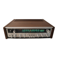
Related product manuals