8
Connections on PCB
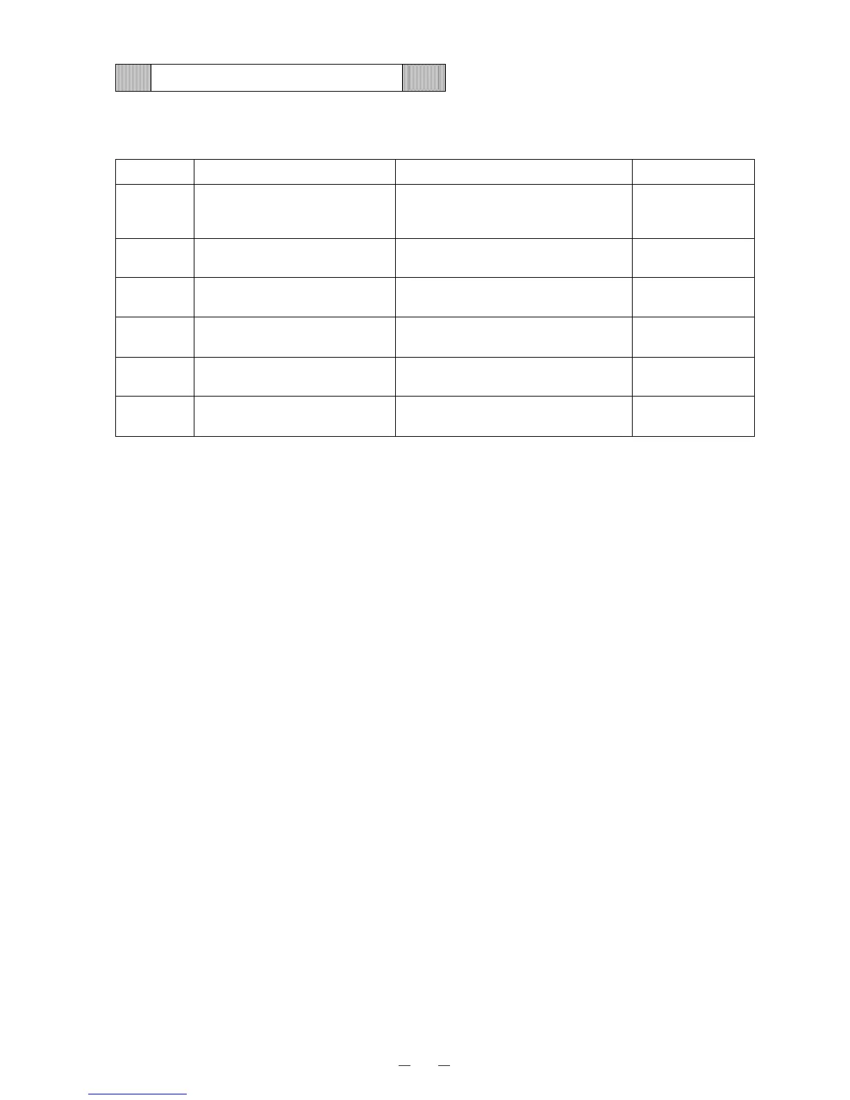
Following table shows the connections on Temp. control PCB.
Connector Connects to Usage Voltage
CN1 Power transformer
To supply the power to Temp.
control PCB.
㧏1-㧏2:10.3VAC
㧏3:GND
㧏4-㧏5:18.5VAC
CN2 #1-#2: Battery, Battery SW
To supply the power to alarm during
power failure.
㧏1:6VDC
㧏2㧦GND
CN3 #1-#3: Temp. sensor To detect chamber temperature.
CN5 #1-#2: Comp. protect sensor
To protect compressor from fan
motor lock (malfunction).
CN6 #1-#5: Remote alarm terminal To output from remote alarm
CN8 #1-#2: Temp. control relay To control chamber temperature
㧏1-㧏2㧦12VDC
 Loading...