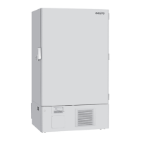
Do you have a question about the Sanyo MDF-U55V and is the answer not in the manual?
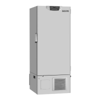
Identifies the specific model covered by this service manual and its voltage/frequency specifications.
Details external/internal dimensions, exterior/interior finishes, and insulation type.
Lists compressor types, refrigerants, oils, and refrigeration system type.
Lists included accessories like keys and scrapers, and optional components.
Covers temperature controller, setting range, display, and sensor type.
Details various alarms (high/low temp, door, power failure) and their triggers.
Explains control panel buttons, key lock, and self-diagnosis.
Specifies maximum cooling performance and temperature control range.
Lists power source, rated power consumption, noise level, and max pressure.
Provides detailed graphical representation of unit dimensions.
Illustrates the flow of the cascade refrigeration system with components.
Lists detailed specifications for compressors, condensers, and evaporators.
Details capillary tube specs, refrigerant type, and dryer components.
Shows the physical layout of components on the main control PCB.
Identifies connectors and their associated functions or terminals.
Explains the purpose and connection points for each PCB connector.
Lists electrical specifications for compressors, starting relays, and capacitors.
Details specifications for various sensors, switches, and the power supply unit.
Provides temperature vs. resistance data for the 502AT-1 sensor.
Lists resistance values for the PT10000 temperature sensor.
Presents a comprehensive diagram of all electrical connections within the unit.
Details the electronic schematic of the main control board, including ICs and components.
Explains the function of control panel keys and status codes.
Covers setting the chamber temperature and activating the key lock function.
Details how to enter and operate various function modes.
Lists and explains error codes related to sensor failures.
Details error codes for battery issues and abnormal compressor temperature.
Explains the operation of door, high temp, and low temp alarms.
Describes the unit's response to power interruptions and recovery.
Explains display codes for various sensor temperatures.
Details display codes for battery and fan motor accumulation times.
Outlines calibration steps for temperature and cascade sensors.
Describes how to display the unit's model code.
Details the F18 function for controlling the capillary heater.
Explains how to set the serial communication ID.
Covers setting communication mode and baud rate.
Describes how to display the unit's power supply voltage.
Explains how to link remote alarms with the buzzer.
Details setting the ring back time for audible alarms.
Explains functions for displaying running ratio and overload diagnostics.
Covers delay settings for measuring and diagnosing running ratio.
Explains how to view the unit's ROM version.
Details setting the buzzer for filter alarms and fan motor accumulation display.
Describes how to adjust the power supply voltage display.
Explains setting the delay time for various alarms.
Details the operational cycles and ON/OFF conditions for compressors H and L.
Explains protection features for compressor H and filter sensor temperature.
Visually represents the ON/OFF timing and conditions for compressors H and L.
Details settings for compressor and temperature alarm delay times.
Explains delay settings for door and power failure alarms.
Describes the purpose and action of the capillary heater to prevent oil logging.
Lists sensor offset values and notes on their adjustability.
Explains the switching behavior of the remote alarm contact in different conditions.
Outlines system actions and settings upon power supply.
Describes how the unit behaves after recovering from a power failure.
Details the function and status of lamps on the control PCB.
Explains the meaning of lamps on the display PCB.
Shows examples of how chamber and set temperatures are displayed.
Illustrates examples of function mode, error codes, and key lock displays.
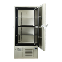
Shows the physical locations of the control panel, door handles, and latches.
Identifies the placement of internal sensors and the filter.
Illustrates the locations of components within the cooling unit.
Shows the arrangement and identification of components inside the electric box.
Presents temperature distribution data across various points at -80°C setpoint and 20°C ambient.
Presents temperature distribution data across various points at -80°C setpoint and 30°C ambient.
Shows power consumption data at -80°C setpoint for different ambient temperatures.
Details temperature uniformity at -70°C setpoint and 20°C ambient.
Details temperature uniformity at -70°C setpoint and 30°C ambient.
Graphs showing temperature fluctuations during cycle operation at -80°C/30°C.
Graphs showing temperature fluctuations during cycle operation at -80°C/20°C.
Graphs showing pull-down temperatures with a simulated load.
Illustrates temperature changes when setpoint is altered with sample load.
Graphs showing pull-up temperatures after a sample load test.
| Model | MDF-U55V |
|---|---|
| Category | Freezer |
| Type | Ultra-Low Temperature Freezer |
| Frequency | 50Hz |
| Number of Doors | 1 |
| Power Supply | AC |
| Voltage | 220V |