-60-
Electrical Adjustment
[Adjustment Condition]
● Input signal
Video signal .......................
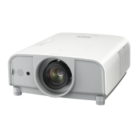
1.0Vp-p/75W terminated, 16 steps gray scale
(Composite video signal)
Computer signal ................... 0.7Vp-p/75W terminated, 16 steps gray scale
pattern
Component Video signal ...... 0.7Vp-p/75W terminated, 16 steps gray scale
(Component video signal with 480p, 575p,
720p or 1080i format)
● Picture control mode ........
“STANDARD” mode unless otherwise noted.
Note:
* Please refer to “Service Adjustment Menu Operation” for entering the service mode and adjusting the service data.
Circuit Adjustments
CAUTION: The each circuit has been made by the fine adjustment at factory. Do not attempt to adjust the following
adjustments except requiring the readjustments in servicing otherwise it may cause loss of performance
and product safety.
16 steps gray scale pattern
WARNING : USE UV RADIATION EYE AND SKIN
PROTECTION DURING SERVICING.
CAUTION:
To prevent suffer of UV radiation, those adjustments
must be completed within 25 minutes.
z Fan Voltages adjustment
1. Enter the service mode.
2. Connect a digital voltmeter to test point
A (+) and
chassis ground (-). (6 test points are provided for this
adjustment, perform all the voltage adjustments in
the table below.)
3. Select group no. “250”. Select item no. B and change
data value to adjust the voltage to be C ±0.05V, and
select item no. D and change data value to adjust
the voltage to be E ±0.05V.
4. Repeat step 2 to 3 for the remaining test points in
the table below.
Test Point A Item B Voltage C Item D Voltage E
TPFAN1 0 4.5 1 13.8
TPFAN2
2 4.5 3 13.8
TPFAN3 4 4.5 5 13.8
TPFAN4 6 4.5 7 13.8
* Before setting, you need to check which type of LCD pan-
el is placed on the projector according to the item "LCD
Panel/Prism Ass'y removal" in the chapter "Optical Parts
Disassembly".
1. Enter the service mode.
2. Panel Type Check
Select group no. “290”, item no. “0”. Check the data
value as follows;
Data value: 0 For L-Type of LCD Panel
Data value: 20 For R-Type of LCD panel
3. Panel Type Setting
Select group no. “290”, item no. “1” and change data
value from 10 to 0 or 20 depending on your LCD Panel
type. When the data value reaches 0 or 20, it returns
to 10 quickly. The gamma-characteristics changes ac-
cording to your selection.
x Panel Type Check and Setting