Do you have a question about the Sanyo PLC-XT20 and is the answer not in the manual?
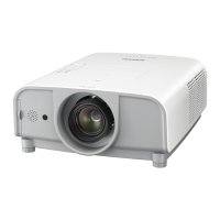
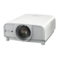
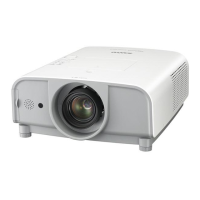
Service manual for the Multimedia Projector.
Important safety measures to be observed during servicing.
Guidelines for safe component replacement emphasizing safety significance.
Warnings for service personnel regarding lamp and high voltage hazards.
Comprehensive technical details covering mechanical, panel, signal, optical, interface, audio, power, and environment specs.
Location and replacement procedure for the projector's fuse.
Function of the thermostat for internal temperature monitoring.
Role of the lamp cover switch in projector operation.
Details on temperature sensors monitoring internal components.
Detection circuits for power failure and fan lock conditions.
Procedure for cleaning the projector's air filter.
Steps to reset the filter usage counter via the menu.
Step-by-step guide for replacing the projection lamp.
Procedure to reset the lamp replacement counter after replacement.
Method to view the total operating hours of the projection lamp.
Procedures for easily accessible maintenance tasks.
Function to prevent accidental operation of projector motors.
How to reset security functions like Key lock and PIN code lock.
Steps to remove the cabinet top assembly.
Further steps for removing the cabinet top assembly.
Additional steps to remove the cabinet top assembly.
Final steps for removing the cabinet top assembly.
Procedure for removing the AV panel and side panel.
Steps to remove the shield plate located at the top.
Initial steps for removing the main board assembly.
Second stage of main board assembly removal.
Third stage of main board assembly removal.
Procedure for removing the lamp assembly.
Initial steps for removing the lens cover assembly.
Second stage of lens cover assembly removal.
Steps to remove the optical engine unit.
Procedure for removing the bottom part of the lens cover.
Initial removal steps for AV and network joint boards.
Second removal steps for AV and network joint boards.
Third removal steps for AV and network joint boards.
Final removal steps for AV and network joint boards.
Initial steps to remove the thermostat assembly.
Second steps to remove the thermostat assembly.
Initial steps to remove the exhaust fan assembly.
Second steps to remove the exhaust fan assembly.
Procedure for removing the exhaust fan duct.
Initial steps to remove the ballast power board assembly.
Second steps to remove the ballast power board assembly.
Procedure for removing the main power board assembly.
Initial steps to remove the filter power board assembly.
Second steps to remove the filter power board assembly.
Initial steps to remove the intake fan assembly.
Second steps to remove the intake fan assembly.
Third steps to remove the intake fan assembly.
Procedure for removing the bottom shield plate.
Steps to disassemble the lamp cover assembly.
Removal of lamp cover switch and R/C front board.
Procedure for removing the projector lens.
Steps to remove the LCD panel and prism assembly.
How to identify and check the type of LCD panel/prism assembly.
Procedure for removing polarized and pre-polarized glass components.
Steps to remove the lens mount.
Procedure for removing the lens shift assembly.
Steps to remove the condenser lens assembly.
Procedure for removing the relay lens assembly.
Removal of green polarized glass and optical filter assemblies.
Removal of blue polarized glass and optical filter assemblies.
Removal of red polarized glass and optical filter assemblies.
Procedure for removing the blue pre-polarized glass.
Initial steps for removing the optical base top.
Second steps for removing the optical base top.
Third steps for removing the optical base top.
Steps to disassemble the FN903 fan assembly.
Diagram showing the location and orientation of optical parts.
Table detailing adjustments required after replacing optical or electrical components.
Procedure for adjusting the optical axis of the projector.
Steps to adjust the contrast using the POL component.
Steps to adjust the contrast using the WV component.
Detailed steps for condenser and relay lens optical axis adjustment.
Procedure to adjust condenser lens for shading.
Steps to adjust relay lens for color uniformity.
Second stage of condenser lens adjustment for color uniformity.
Adjusting contrast for the Green polarized glass unit.
Adjusting contrast for the Blue polarized glass unit.
Adjusting contrast for the Red polarized glass unit.
Adjusting contrast for different polarized glass units using WV lever.
How to enter and navigate the service adjustment menu.
Notes and cautions regarding memory IC replacement and re-adjustments.
Precautions and overview for adjusting internal circuits.
Adjusting fan voltage levels via service menu.
Checking and setting the projector's LCD panel type.
Adjusting PC signal gain for color uniformity.
Automatic calibration for PC video signals.
Automatic calibration for composite video signals.
Automatic calibration for 480i component video signals.
Adjusting pedestal level for PC signals.
Adjusting composite video signal gain.
Adjusting 480i component video signal gain.
Adjusting common center for proper image alignment.
Adjusting PC signal luminance at 50%.
Adjusting video signal luminance at 50%.
Adjusting white balance for PC signals.
Adjusting white balance for video signals.
Adjusting white uniformity using external software.
Calibrating the filter after replacement or cleaning.
Diagram showing locations of test points on the main board.
Table listing initial values and ranges for service adjustments.
Overview of the projector's main chassis components and connections.
Block diagram of the input and signal processing circuitry.
Block diagram illustrating the LCD panel drive circuitry.
Block diagram of the audio signal processing path.
Block diagram of the lamp control circuitry.
Block diagram detailing the fan control system.
Block diagram of the motor control system for focus, zoom, and lens shift.
Block diagram illustrating the bus control system.
Block diagram of LED indicators and remote control interface.
Diagram of the power supply and its failure detection circuits.
Table correlating indicator lights with projector operational status.
Explanation of the WARNING FILTER indicator and its causes.
Explanation of the LAMP REPLACE indicator and actions to take.
Overview of the power failure detection mechanism.
Information on identifying power failure causes via signals.
Flowchart illustrating power failure detection paths and error information.
Function to check and log projector errors and their descriptions.
Procedure to clear the projector's error history log.
Using RS-232C port for power failure diagnosis and error information retrieval.
Pinout and description for system control I/O ports.
Pinout and description for parallel I/O expander ports.
Pinout and description for IIC bus D/A converter ports.
Pinout and description for parallel bus input expander ports.
Waveform display for the VIDEO signal.
Waveform display for the HSYNC signal.
Waveform display for the VSYNC signal.
Waveform display for the HSYNC signal (HS1).
Waveform display for the VSYNC signal (VS1).
Waveform display for the R-S&H signal.
Waveform display for the G-S&H signal.
Waveform display for the B-S&H signal.
Method for cleaning internal components using air spray.
Detailed cleaning procedures requiring disassembly of optical parts.
Block diagram for the AD8074/AD8075 amplifier and associated ICs.
Block diagram for the AN5870 signal switch IC.
Block diagram for BA6287 motor drive ICs.
Block diagram for BA6920 motor drive ICs.
Block diagram for BA7078 sync separator IC.
Block diagram for FA7711V DC-DC controller IC.
Block diagram for HIN202EIB RS-232C driver IC.
Block diagram for L3E01060 level shift ICs.
Block diagram for L3E06150 sample & hold ICs.
Block diagram for L3E07110 digital gamma shift & LCD driver IC.
Block diagram for LM4889 audio output IC.
Block diagram for NJW1141 audio control IC.
Block diagram for TE7783 parallel I/O expander IC.
Block diagram for PW190 scan converter & system control IC.
Explains how to read capacitor and resistor specifications and their materials.
Diagram showing the physical location of major electrical components on assembled boards.
Diagram illustrating the location of cabinet parts.
Exploded view of the optical engine with lens shift assembly.
Exploded view of the optical engine with lens assembly.
Exploded view of the condenser lens assembly.
Exploded view of the relay lens assembly.
Exploded view of the LCD panel and prism assembly, noting type differences.
Diagram of the polarized unit, indicating different color types and notes.
Diagram illustrating the arrangement of optical parts within the unit.
Reference to available schematic diagrams for various projector models.
Reference to available printed wiring board diagrams.
Guide to understanding part specifications, types, and readings in diagrams.
Illustrations of pin configurations for diodes, transistors, and ICs.
Guidelines and precautions for soldering, emphasizing lead-free practices.
Layout diagrams for R/C front and network joint boards.
Printed wiring board layout for the main board, side A.
Printed wiring board layout for the main board, side B.
| Projection technology | LCD |
|---|---|
| Contrast ratio (typical) | 1000:1 |
| Projector native resolution | XGA (1024x768) |
| Resolution | 1024 x 768 pixels |
| Dimensions (WxDxH) | 302 x 422 x 162 mm |
| Display diagonal | 1 \ |
| Lamp type | UHP |
| Lamp power | 300 W |
| Light source type | Lamp |
| Market positioning | Portable |
| Weight | 9200 g |
|---|