Control of W-ECO MULTI SYSTEM
3
TD831077
III - 66
7 Basic wiring diagram
Make correct wiring without
any mistakes (incorrect
wiring will damage the
equipment).
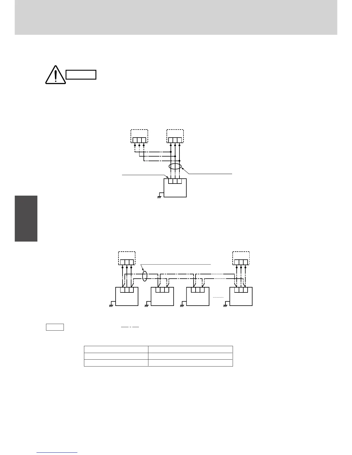
2. Optional Controller (simplified remote controller)
¶ Following is a wiring diagram for controlling one indoor unit by two simplified remote controllers.
12
Option
3 12
Option
3
12
Indoor
Unit
Earth
3
Remote controller wiring
3-pin terminal block for
remote controller wiring
Simplified remote
controller (main)
Simplified remote
controller (sub)
1508_T_I
¶ Performing the group control of the multiple indoor units with two simplified remote controllers.
* The main and the sub simplified remote controllers can be installed at any indoor unit for operations.
12
Indoor Unit
No. 8
Earth
312
Indoor Unit
No. 3
Earth
312
Indoor Unit
No. 2
Earth
3
12
Option
3
Simplified remote
controller (sub)
12
Option
3
Simplified remote
controller (main)
3-pin terminal
block for remote
controller wiring
Inter indoor units wiring for group control
12
Indoor Unit
No. 1
Earth
3
1509_T_I
NOTE
1) The chain lines ( ) indicate control line in the system.
2) Up to two system controllers are connectable in one control line system.
3) Recommended wire diameter and wire length
CAUTION
Remote control wiring Control wiring for group control
0.75 mm
2
(AWG #18) 0.75 mm
2
(AWG #18)
Max. 500 m (Total) Max. 500 m (Total)
 Loading...