II - 20
Design of W-ECO MULTI SYSTEM
2
TD831077
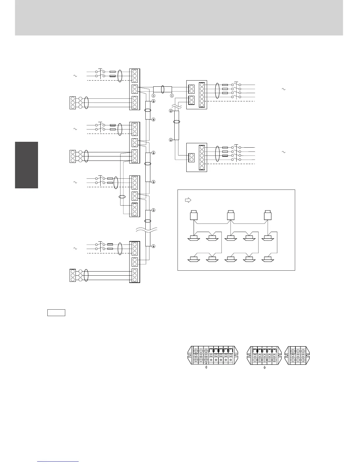
3. Electrical Wiring
3-3. Wiring system diagrams
(1) Refer to Section 5-2. “Recommended Wire Length and
Wide Diameter for Power Supply System” for the
explanation of “A”, “B”, “C”, “D”, and “E”, in the above
diagrams.
(2) The basic connection diagram of the indoor unit shows
the 8P terminal board, so the terminal boards in your
equipment may differ from the diagram.
(3) R.C. Address should be set before turning the power
on.
(4) Regarding the R.C. Address setting, refer to page 86.
Auto. address setting can be executed by a remote
controller automatically. Please refer to the ENGI-
NEERING MANUAL & TECHNICAL DATA of the ECO
MULTI SYSTEM.
2
1
3
1
2
3
1
2
2
1
2
1
2
1
3
4
5
6
2
1
3
WHT
RED
Remote
controller
D
BLK
2
1
3
2
1
3
1
2
3
1
2
2
1
3
1
2
3
1
2
2
1
3
1
2
3
1
2
2
1
3
WHT
RED
Remote
controller
Group control:
D
BLK
2
1
3
2
1
3
WHT
RED
Remote
controller
D
A
E
Indoor
unit (No. n)
Indoor
unit (No. 1)
Indoor
unit (No. 2)
Indoor
unit (No. 3)
C
B
Outdoor unit
PC unit
L1
Power supply
L2
L3
380-415V-3N 50Hz
N
Ground
Ground
L
N
L
N
L
N
L
N
1701_M_I
BLK
2
1
3
2
1
2
1
3
4
5
6
Outdoor unit
AD unit
Power supply
220-240V 50Hz
B
B
B
Ground
Ground
Ground
A
L1
Power supply
L2
L3
N
Ground
380-415V-3N 50Hz
Power supply
220-240V 50Hz
Power supply
220-240V 50Hz
Power supply
220-240V 50Hz
Ground
C
Ground
C
Ground
C
Ground
C
Ground
NOTE
1(L)2(N)
Power
supply
U1
Inter-unit
control wiring
U2
Remote
controller
8P terminal board
0511_M_I
R1R2 R3
1 2 U1 U2 R1 R2 R3
AS, SL, S, X, T, U,
D, F, FM Type
K Type
1(L)2(N)
45
12345
123
Power
supply
Inter-unit
control wiring
Remote
controller
5P terminal board + 3P terminal board
0512_M_I
R.C. 1
Recommended Inter-Units control wiring
Wire along with ref. piping to perform test run easily
Indoor unit address
1-21-1 2-1 2-2 3-1
1-41-3 2-3 2-4 3-2
R.C. 2 R.C. 3
Refrigerant
circuit no.
1784_M_I
 Loading...