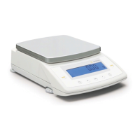
The indicator is equipped with the
following data interfaces:
– COM1: Standard interface (RS-232)
– UniCOM: Universal data interface
(optional)
Both of these interfaces can be con-
figured in the Setup menu for various
input/output functions (e.g., Printer,
second weighing instrument, PC,
checkweighing/classification display).
The optional UniCOM interface can
be used for RS-232, RS-485 or RS-422
communication, or as voltage-/current
(analog) interface. A bar code scanner
(Combics 2 only) or an external recharge
-
able battery pack can be connected
to the female UniCOM port (on CW1S,
CW1NS and CW2S models, use the
corresponding terminal screws).
Features
– Indicator models CW1P, CW1NP and
CW2P (IP44 protection):
Connect via a 25-contact D-Sub
female connector.
Use a T-connector (see “Accessories")
to connect a second device to the same
interface.
– Indicator models CW1S, CW1NS,
CW1FS, CW1NFS, CW2FS, CH1NE,
CH1NG and CW2S (IP67 protection):
Route connecting cable from the
peripheral device to the indicator via
a cable gland. Then connect the free
ends of the cable using the terminal
screws.
If you wish to connect a second peri-
pheral device to the same interface port,
use a separate cable gland to route
the connecting cable of this device into
the indicator.
!Warning When Using RS-232
Connecting Cables Not Supplied by
Sartorius:
The pin assignments in the cable
might not be compatible with Sartorius
equipment. Check all pin assignments
against the cabling diagrams and dis-
connect any lines that are not assigned.
Failure to do so may damage or even
completely ruin your indicator and/
or peripheral device.
79
Data Interfaces
Specifications
Serial interface:
Operating mode: Full duplex
Standard: COM1: RS-232,
UniCOM
1
): RS-232 or RS-422/RS-485
Interface connector: CW1P, CW1NP and CW2P (IP44 protection):
25-contact D-Sub female connector
CW1S, CW1NS and CW2S (IP67 protection):
The cable is connected to terminal screws inside the housing
and routed into the housing via a cable gland.
Transmission rates: 150, 300, 600, 1200, 2400, 4800, 9600 and 19,200 baud
(depending on the operating mode)
Number of data bits: 7 or 8 bits
Parity: Space, odd, even, none (depending on the operating mode)
Number of stop bits: 1 or 2 stop bits
Handshake mode: Software (XON/XOFF) or hardware (1 character after CTS)
Communication mode: SBI, XBPI-232
2
), XBPI-485
1
)
2
), MP8 binary
3
), SMA
Available printers: – YDP01IS
– YDP02IS-Label
– YDP01IS-Label
– Universal
– YDP02
– YDP04IS
– YDP03
– YDP04IS-Label
– YDP02IS
– YAM01IS Alibi memory
Network address
4
): 0, 1, 2, (…), 31
SBI: Manual data output: Without stability, after stability, configurable printout
SBI: Automatic
data output: Without stability, at stability, at user-defined intervals
SBI: Output format: 16 or 22 characters
Printout of application
data: Output of a configurable printout
Analog UniCOM interface (optional)
Standard: 4 to 20 mA, 0 to 20 mA, 0 to 5V
Power supply: Internal or external
Factory setting: 4 to 20 mA, internal power supply
Interface connector: CW1P, CW1NP and CW2P indicators (IP44 protection):
25-contact D-Sub female connector
CW1S, CW1NS and CW2S indicators (IP67 protection):
The free ends of the cable are connected to terminal
screws inside the housing; the cable is routed into
the housing via a cable gland.
1
) Optional UniCOM universal data interface
2
) XBPI operating mode: 9600 baud, 8 data bits, parity: odd, 1 stop bit
3
) Only with the standard COM1 interface
4
) Network address is valid only in the XBPI mode