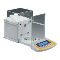
Do you have a question about the Sartorius Gem GE412 and is the answer not in the manual?
Requirements for using service software for adjustments and avoiding outdated versions.
Lists Sartorius service software, BPI connection, and RS232 cables with part numbers.
Lists required weight sets (accuracy, grams, catalog no.) for models TE214S, TE212, TE124S, GD603, TE64, TE313S, GD103, GD252.
Lists required weight sets for TE153S, TE153S-DS, TE612, TE612-L, TE412, TE412-L, GE412.
Lists required weight sets for GE812, TE1502S, GE2102, GE1302, TE3102S.
Lists required weight sets for TE6101, TE4101, GE4101, GE7101, TE2101, GE2101, TE601, GE811.
Lists required weight sets for TE12000, TE6100, TE4100 models.
BPI mode must be activated before working with service software for adjustments.
Procedure including disconnecting power, removing parts, and connecting cables.
Steps to replace pan, turn on, press button for self-test, and wait for BPI mode.
Lists items to check and adjust: overload stop, zero point, repeatability, off-center error, span, linearity.
Overload stops checked after strain-gauge system replacement; requires service software.
Steps to activate BPI mode, use diagnostics program, adjust stop, and close function.
Lists test weights and their permissible tolerance (±10%) for various models.
Instructions to open, connect power, add weight (6500g + test weight), adjust stop screw, and verify stability.
Explains why zero-point offset adjustment is needed (e.g., after PCB replacement, span adjustment issues).
Procedure involving opening the balance, connecting a voltmeter to IC15, and testing preload voltage.
Table mapping zero-point offset voltage ranges to R29 resistance values (ohms).
Procedure to check repeatability using test weights and calculating S = (Max - Min) / 3.
Steps to check off-center error by placing test weight in different positions (1-5) and zeroing.
Procedure for adjusting off-center error by filing thin parts or using adjustment screws.
Two methods described: using service software or manual calibration routine.
Steps for manual span adjustment: select menu, zero balance, press TARE, center weight.
Linearity check according to WKD-038, in 4-g steps, comparing displayed values to tolerances.
Procedure using service software: activate BPI, connect PC, run linearity program, test span.
Procedure for checking repeatability using test weights, similar to strain gauge systems.
Refers to "Adjustment Datasheet" and details placing test weights on triangular pans.
Details placing test weights on square pans and adjusting balance if error is too large.
Steps for adjusting off-center loading error in double-lever systems using a 3-point measurement.
Procedure to place test weight in positions A, B, C and record readings.
How to adjust screws inwards (negative) or outwards (positive) based on greatest deviation.
Describes careful filing at thin places on the upper guide for models TE, GD, TE3102S.
Recommends replacing the entire subassembly rather than attempting component-level repairs.
Suggests reading out and storing the balance/scale's data record before replacing the main PCB.
Steps to open, disconnect cables, remove screws, old PCB, transfer resistor, install new PCB, and reprogram.
| Maximum Capacity | 410 g |
|---|---|
| Readability | 0.01 g |
| Pan Size | Ø 120 mm |
| Calibration | External |
| Display | LCD |
| Power Supply | 115/230 V, 50/60 Hz |
| Linearity | ±0.02 g |
| Response Time (typical) | 2 seconds |
| Weighing Units | g, ct, dwt, oz, lb |
| Interface | RS-232 |
| Operating Temperature | 10°C to 30°C |
| Weight | Approximately 1.5 kg |
| Repeatability (Std. Dev.) | ≤ 0.01 g |


