ISBBS, ISDCS Operating Instructions
7
Data Interface
The weighing platform has a standard COM1 interface, RS-485 socket (IP65).
The standard COM1 interface can be converted to RS-232 through the
Sartorius Service Center.
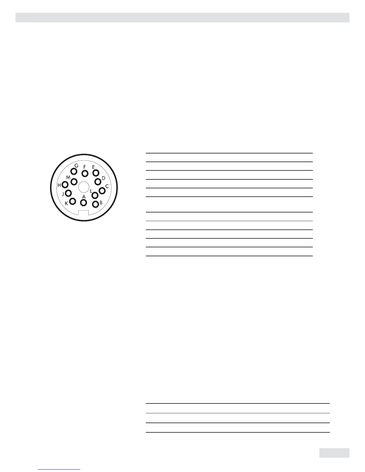
Pin Assignment
COM 1 round plug connector with screw connection.
Front view:
RS-485 data interface RS-232 data interface
A RxD–TxD–N Not used
B Not used RxD
C Not used TxD
D Not used CTS
E GND GND
F Menu access switch
for adjustment
Menu access switch
for adjustment
G 12-30 VDC 2W supply 12-30 VDC 2W supply
H Not used DTR
J GND GND
K GND GND
L RxD–TxD–P Not used
M 12-30 VDC 2W supply 12-30 VDC 2W supply
h Female Interface Connector (Recommended):
Type C091D, 12-pin, Amphenol (IP65) cable type as per AWG 24
Observe power supply instructions.
Operation as an RS485-interface:
Switch 4 must be open in order to switch to RS-485 operation (factory setting).
Where applicable, deactivate bias resistors for RS-485 operation. Open switches
for this purpose (factory setting).There must only be one instance of bias
resistors per transmission path (network orpoint-to-point connection). Otherwise
there is a risk of transmission errors. Where applicable, refer to the specifications
or circuit documentation for the remote station or network nodes in question.
Bias resistors must always be activated or deactivated in pairs. The terminating
resistor (transmitting side, switch 1 must be activated if the device is located at
either end of an RS-485 bus system, or where it is connected to another device
in a point-to-point link. There must also be a terminating resistor of 120 Ω in
place at the remote station. Where applicable, activate terminating resistor 120
Ω for RS-485operation:
Terminating resistor, receiving side 120 Ω Switch 1 on
BIAS resistor, receiving side (RxD+, pull-up) 680 Ω Switch 2 on
BIAS resistor, receiving side (RxD–, pull-down) 680 Ω Switchr 3 on
No function Switch 4
Data Interface