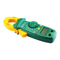
This document describes the SATA 03022 Digital Clamp Multimeter, a 3 3/4-digit auto-ranging digital clamp meter designed for various electrical measurements. It conforms to IEC-61010, Pollution Degree 2, and Overvoltage Category CAT III 600V standards, ensuring safe operation within specified limits.
Function Description:
The SATA 03022 is a versatile measuring tool capable of measuring AC/DC voltage, AC/DC current, resistance, capacitance, and frequency. It also includes functions for diode testing and circuit continuity. Key operational features include relative value measurement, data hold, low battery voltage indication, overrange indication, and automatic power-off.
Important Technical Specifications:
- Display: 3 3/4-digit LCD with a maximum reading of 9999 for frequency measurement.
- Sampling Rate: Approximately 3 times per second.
- Polarity Indication: Automatic negative polarity indication with a "-" symbol on the screen.
- Overrange Indication: "OL" displayed on the screen (except for voltage ranges).
- Clamp Head Opening: Maximum diameter of 30mm (approximate value).
- Predictive Current Lead Dimension: Maximum diameter of 28mm (approximate value).
- Low Battery Indication: A battery symbol appears on the screen.
- Power Supply: 2 x 1.5V AAA batteries.
- Operating Temperature: 0°C to 40°C, with relative humidity less than 75%.
- Storage Temperature: -10°C to 50°C, with relative humidity less than 85%.
- Dimensions: 202.5mm x 73.5mm x 40mm.
- Weight: Approximately 220g (including battery).
- Accuracy Guarantee: 1 year, under operating conditions of 18°C to 28°C and relative humidity less than 75%. Accuracy is expressed as ±(% reading + least significant digit).
Measurement Ranges and Accuracy:
- AC Voltage:
- 4.000V: 1mV resolution, ±(0.8% +5) accuracy.
- 40.00V: 10mV resolution, ±(0.8% +5) accuracy.
- 400.0V: 0.1V resolution, ±(1.2% +5) accuracy.
- 600V: 1V resolution, ±(1.2% +5) accuracy.
- DC Voltage:
- 400.0mV: 0.1mV resolution, ±(0.8% +5) accuracy.
- 4.000V: 1mV resolution, ±(0.8% +5) accuracy.
- 40.00V: 10mV resolution, ±(0.8% +5) accuracy.
- 400.0V: 0.1V resolution, ±(1.0% +5) accuracy.
- 600V: 1V resolution, ±(1.0% +5) accuracy.
- AC Current:
- 40.00A: 0.01A resolution, ±(2.5% +6) accuracy.
- 400.0A: 0.1A resolution, ±(2.5% +6) accuracy.
- 600A: 1A resolution, ±(2.5% +6) accuracy.
- DC Current:
- 40.00A: 0.01A resolution, ±(3.0% +10) accuracy.
- 400.0A: 0.1A resolution, ±(3.0% +6) accuracy.
- 600A: 1A resolution, ±(3.0% +6) accuracy.
- Resistance:
- 400.0Ω: 0.1Ω resolution, ±(1.0% +5) accuracy.
- 4.000kΩ: 1Ω resolution, ±(1.0% +5) accuracy.
- 40.00kΩ: 10Ω resolution, ±(1.0% +5) accuracy.
- 400kΩ: 100Ω resolution, ±(1.0% +5) accuracy.
- 4.000MΩ: 1kΩ resolution, ±(1.5% +5) accuracy.
- 40.00MΩ: 10kΩ resolution, ±(3.0% +10) accuracy.
- Capacitance (using relative value measurement):
- 40nF: 10pF resolution, ±(5.0% +5) accuracy.
- 400nF: 100nF resolution, ±(5.0% +5) accuracy.
- 4μF: 1nF resolution, ±(5.0% +5) accuracy.
- 40μF: 10nF resolution, ±(5.0% +5) accuracy.
- 100μF: 100nF resolution, ±(5.0% +5) accuracy.
- Frequency:
- 9.999Hz: 0.001Hz resolution, ±(1.0% +5) accuracy.
- 99.99Hz: 0.01Hz resolution, ±(1.0% +5) accuracy.
- 999.9Hz: 0.1Hz resolution, ±(1.0% +5) accuracy.
- 9.999kHz: 1Hz resolution, ±(1.0% +5) accuracy.
- 99.99kHz: 10Hz resolution, ±(1.0% +5) accuracy.
- 200kHz: 100Hz resolution, ±(1.0% +5) accuracy.
Usage Features:
-
Panel Introduction:
- Head: Used to clamp the measured conductor, which should be centered in the head during measurement.
- Head Trigger: Controls the opening and closing of the clamp head.
- "REL/ZERO" Button: Functions as a zero-setting button for DC current measurements (displaying zero and deactivating zero-clearing mode with a second press). Also used to enter and exit relative value measurement mode.
- "Function Selection" Button: Selects between AC/DC voltage, AC/DC current, and resistance/diode/continuity/capacitance measurement functions.
- Display: LCD screen for readings.
- COM Jack: Input for the black test probe.
- VΩHz Jack: Input for the red test probe.
- Backlight Button: Press and hold for approximately 2 seconds to turn the backlight on/off.
- Function/Position Switch: Selects desired function or range, and powers the meter on/off.
- "HOLD" Button: Activates/deactivates data hold mode, indicated by an "H" symbol on the screen.
- Insulated Gate: Provides a protective distance at the jaw to reduce the risk of finger contact with the head or measured conductor. Fingers should not extend beyond this gate when holding the meter.
-
Operation Instructions:
- Data Hold: Press "HOLD" to freeze the current reading; press again to release.
- Relative Value Measurement: Set the meter to the desired function/range, take a reading, then press "REL/ZERO" to store it as a reference (display shows zero and "△"). Subsequent readings show the difference from the reference. Press "REL/ZERO" again to exit. (Note: Actual measured value should not exceed the maximum measurable value of the range. Not applicable for frequency measurement.)
- DC Voltage Measurement: Connect black probe to "COM", red probe to "VΩHz". Set function switch to "V" and press "Function Selection" until "DC" symbol appears. Connect probes to the circuit and read. Polarity of the red probe connection is indicated. (Caution: Do not apply voltage greater than 600V to input terminals.)
- AC Voltage Measurement: Connect black probe to "COM", red probe to "VΩHz". Set function switch to "V" and press "Function Selection" until "AC" symbol appears. Connect probes to the circuit and read. (Caution: Do not apply voltage greater than 600V to input terminals.)
- DC Current Measurement: Remove all probes. Set function switch to desired current range. If reading is not zero, press "REL/ZERO" before clamping. Press trigger, clamp conductor in the center of the head, slowly release trigger until head is fully closed. Read. (Note: Only measure one conductor at a time to avoid errors.)
- AC Current Measurement: Remove all probes. Set function switch to desired current range. Press trigger, clamp conductor in the center of the head, slowly release trigger until head is fully closed. Read. (Note: Only measure one conductor at a time to avoid errors.)
- Resistance Measurement: Connect black probe to "COM", red probe to "VΩHz". Set function switch to "Ω" and press "Function Selection" to select resistance. Connect probes to the resistor and read after stabilization. (Note: High resistance readings may take several seconds to stabilize. "OL" indicates open circuit. Disconnect power and discharge capacitors before online resistance measurement.)
- Continuity Test: Connect black probe to "COM", red probe to "VΩHz". Set function switch to "Ω" and press "Function Selection" until "Continuity" symbol appears. Connect probes to the circuit. Beeper sounds if resistance is less than 20Ω. (Note: Disconnect power and discharge capacitors before testing.)
- Diode Test: Connect black probe to "COM", red probe to "VΩHz" (red probe is positive). Set function switch to "Ω" and press "Function Selection" until "Diode" symbol appears. Connect red probe to positive pole of diode, black probe to negative pole. Read forward voltage drop.
- Capacitance Measurement: Connect black probe to "COM", red probe to "VΩHz". Set function switch to "Capacitance" and press "Function Selection" until capacitance unit appears. Connect probes to the capacitor. Read after stabilization (large capacitors may take up to 30 seconds). (Note: Fully discharge capacitors before measurement. For small capacitance, use relative value measurement to subtract stray capacitance.)
- Frequency Measurement: Connect black and red probes to "VΩHz" jacks. Set function switch to "Hz". Connect probes to the power or circuit. Read. (Note: Input voltage must be between 1V rms and 20V rms for accurate readings.)
- Automatic Power-Off: The meter automatically powers off after 15 minutes of inactivity. Press the "Function Selection" button to turn it on or wake it from sleep.
Maintenance Features:
- General Maintenance: Do not attempt repairs unless a qualified professional technician with sufficient calibration and repair instructions. Recommended calibration period is 12 months. Wipe the casing with a damp cloth and mild detergent. Avoid abrasives or solvents.
- Terminal Cleaning: Turn off the meter and remove test leads. Shake out any dust from terminals. Use a new cotton ball dipped in alcohol to carefully clean the inside of each input terminal.
- Battery Replacement: When the low battery symbol appears, replace the batteries immediately. Unscrew the battery cover, open it, replace old batteries with new ones of the same type, ensuring correct polarity. Close and secure the cover. (Warning: Remove probes before opening battery cover or casing.)
Unpacking Inspection:
The package contents include:
- 1 set of AC/DC clamp multimeter
- 1 pair of test probes
- 1 piece of operation instruction manual
- 1 piece of warranty card
- 2 pieces of 1.5V AAA batteries
- 1 piece of special zipper bag