Note
To avoid damage to the meter or equipment, please observe the following requirements:
1.Before measuring resistance, continuity, diode and capacitance, switch off the power
of the measured circuit and fully discharge all capacitors.
2.Use the correct terminals, functions and ranges.
3.Remove the probes and head from the measured conductor or circuit before rotating
the function/position switch.
ESPT JARUEN DE KO
03022
Panel introduction
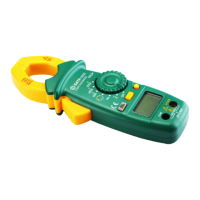
1. Head
It is used to clamp the measured conductor. The measured conductor shall be located
in the center of head during the measurement.
2. Head trigger
It is used to control the opening and closing of the head.
3. "REL/ZERO" button
a)This button acts as a zero setting button during DC measurement. Press this button,
after which the screen will display zero, and then press it again to deactivate the zero
clearing mode.
b)This button can also be used to enter and deactivate the relative value measurement
mode.
4.“Function selection” button
It is used to make selection among the following functions:
a)AC and DC voltage measurement
b)AC and DC measurement
c)Resistance, diode, continuity and capacitance measurement
5. Display
6.“ ” jack
- 17 -