AE5105/AE5105-3
30
中文
EN
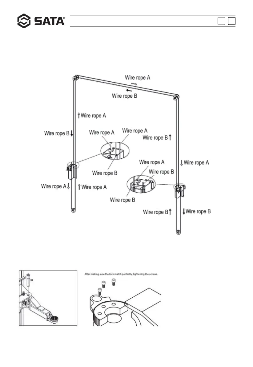
- Installation of balance wire rope
Make sure that the left and right sliding tables are at the first safety position, and then install the balance wire rope as
per the track shown in the figure. Do not tighten the nut temporarily as the tension of two wire ropes will be adjusted
for synchronization later on. Note: The screw rod for the left or right wire rope must be tightened. Make sure that the
left & right sliding tables are locked at the same height during adjustment.
- Installation of bracket arm
Install four bracket arms into the sliding table through the pin, with three-section straight arms at the front end and
two-section straight arms at the back end. (Note: The three-section bracket arms shall be installed at the front end and
each arm is required to be installed with a circlip.)
- Installation of power unit
Install the power unit on the motor board of the main post and fix it with bolts and nuts. Install the limit switch properly
and connect the wires.