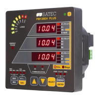
PM130 PLUS QuickStart www.satec-global.com
CONFIGURATION
The essential configuration includes:
1. Basic measurement setup
2. Communication setup and testing
3. Resetting the min/max, energy, demands etc.
Additional recommended configuration: set points, TOU and data logging
Note: It may be easier first to configure communication and use PAS software for setup
Basic Measurement Setup
In any display screen, press SELECT x 3 (until blinks), then press ENTER ( blinks), then
x 2 () and ENTER to enter the Basic Settings Display.
Network wiring configuration
Transformation ratio of the Potential Transformers
Additional PT factor for EHV network
The Primary Rating Of The Current Transformers
(quick access to this parameter: press SELECT, then simultaneous and SELECT)
Duration in minutes of the power demand period calculations
E = External pulse in DI1
The number of blocks to be averaged for sliding window demands
Duration in seconds for voltage and current demand
Max. Demand Load Current in Amperes. 0 = CT primary current.
3-wire 2-element Delta direct connection using 2 CTs
4-wire 3-element Wye direct connection or 3PTs, and 3 CTs
3-wire 2-element Open Delta connection using 2 PTs, 2 CTs
4-wire 2½-element Wye connection using 2 PTs, 3 CTs
3-wire 2½-element Open Delta connection using 2 PTs, 3 CTs
4-wire 3-element Delta direct connection using 3 CTs
3-wire 2½-element Broken Delta connection using 2 PTs, 3 CTs
* LN or LL denotes the default use of L-L or L-N voltages (in thresholds, min/max, demands etc.)
Communication setup and testing
In any display screen, press SELECT x 3 ( blinks), then press ENTER ( blinks),
then x 3 (.) and ENTER to setup the built in RS-485 port (COM1).
If communication module is present, configure also COM2.
Resetting the min/max, energy, demands etc.
In any display screen, press SELECT x 3 ( blinks), then press ENTER ( blinks), then
ENTER to enter the reset menu. Select the value to be reset, press SELECT
to select, then press
ENTER for 5 seconds until the notification is changed to .
WI!
Copyright © 2013 SATEC Ltd.

 Loading...