2
NOTE:
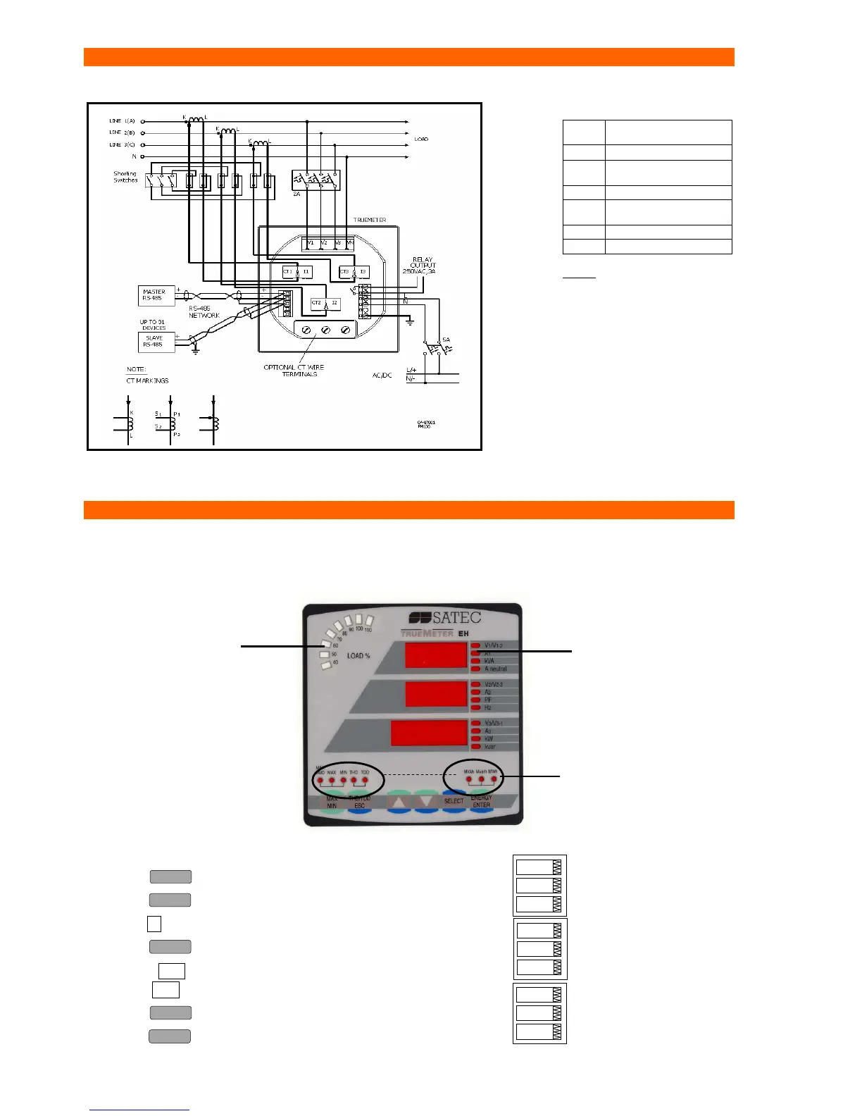
Refer to the User
Guide for the wiring
schematics diagrams
Typical Electrical Installation
Figure 4: Common Wiring Mode: 4LL3 or 4L-n3
*
Elementary Setup
All setups can be performed directly from the display panel or via communications using PAS
communication software, except for Communications and Display setups, which must be performed
directly on the instrument panel.
To set the CT Primary current, perform the following steps:
• Press 3 times: CHG should blink.
• Press 2 times:
• Press ▲ 2 times:
• Press : "5" should blink.
• Use the ▲▼ arrows to scroll to the desired value
(press ▲▼ continuously for quick scrolling).
• Press to save the selected value.
• Press (X3) to return to the display menu.
3OP2
3-wire open delta using 2
CTs
4Ln3∗
∗∗
∗
4-wire Wye using 3 PTs
3dir2
3-wire direct connection
using 2 CTs
4LL3
4-wire Wye using 3 PTs
3OP3
3-wire open delta using 3
CTs
3Ln3
4-wire Wye using 2 PTs
3LL3
4-wire Wye using 2 PTs
bASc
4Ln3
ConF
menu
option
value
bASc
5
Ct
menu
option
value
STA
CHG
OPS
menu
option
value
*connect the ground
PM130 terminals of
the power supply and
of the communication
connectors to the
switchg ear earth
ground, using 1.5
mm
2
/14AWG
dedicated wire.
Small LEDs indicate
measured parameter
Load bar graph, indicates %
Nominal load current
Round LEDs indicate
measurement group

 Loading...


