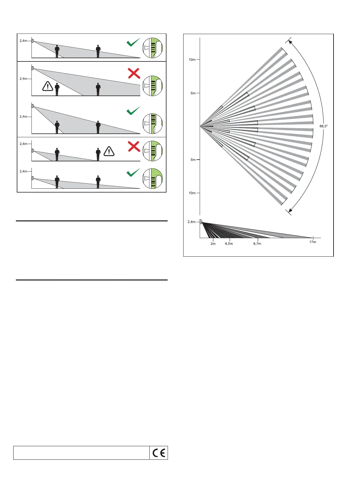
Figure 4. How the mounting height affects the detector supervised area and how
the pyroelectric element should be positioned against the lens to optimize the
area.
Start-up
1. Turn power supply on (the LED will start blinking, which indicates the starting
state).
2. When the detector enters the ready state (the LED stops blinking), carry out
a test for the detector range, i.e. check that a movement within the supervised
area will activate the alarm relay or cause the LED light up. During the test, the
LED ON/OFF pins must be shorted, or the LED input must be shorted to the
common ground.
3. If necessary, change the detector sensitivity.
Technical data
Nominal supply voltage (±15%) .................................................................. 12V DC
Average current consumption (±10%)............................................................ 11mA
Violation signaling time ........................................................................................ 2s
Operating temperature range.................................................................-10...+55°C
Detectable motion speed ....................................................................... up to 3 m/s
Dimensions.........................................................................................62x96x48mm
Recommended mounting height ......................................................................2.4m
SATEL sp. z o.o.
ul. Schuberta 79
80-172 Gdańsk
POLAND
tel. + 48 58 320 94 00
info@satel.pl
www.satel.pl
The latest EC declaration of conformity and certificates are available
for downloading on our website www.satel.pl
Figure 5. Distribution of lens beams.
Note: Effective range of the detector may differ from that shown in the drawing.