www.satlab.com.se
29
SL900 GNSS RTK System
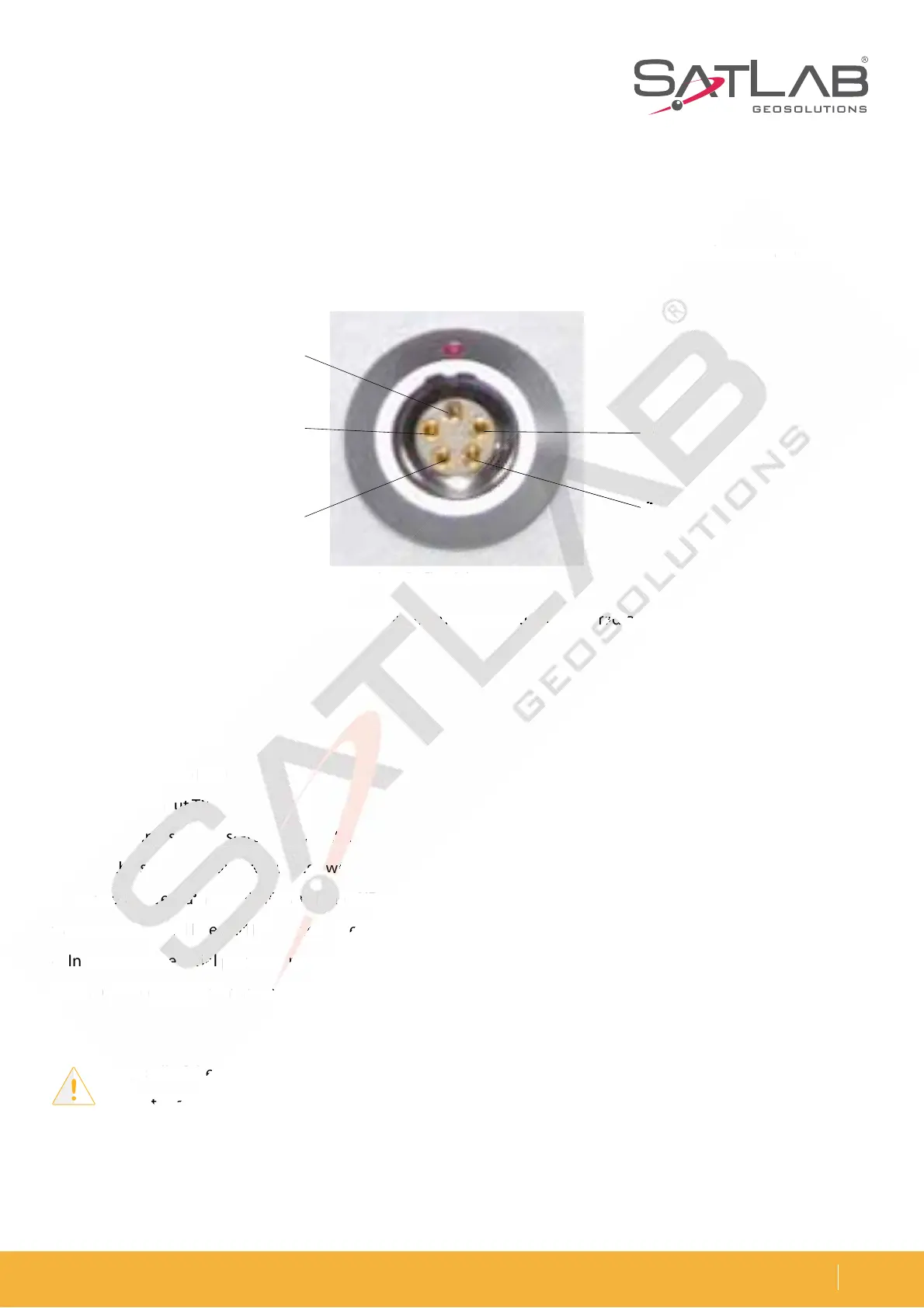
Five-pin Lemo Interface
5IFmWFQJOMFNPDPOOFDUPSJTVTFEGPSUIFDPOOFDUJPOPGUIFSFDFJWFSXJUIBOFYUFSOBMEBUBMJOLBOEPSBOFYUFSOBM
power supply.
1. It is also known as COM, which used to connect the host and external radio to transmit differential data.
Description:
- 1 to GND
- 2 to GND
- 3 power into Vin
EBUBJOUP39%
EBUBPVU59%
2. All the round sockets start to count the stitches counterclockwise on the front side; the round plugs start to
number the stitches counterclockwise with the welding surface.
"MM UIF BCPWF EBUB PVU 59% BOE JO 39% TJHOBMT BSF EFTDSJCFE CZ UIF SFDFJWFS59% JT UIF SFDFJWFS EBUB
USBOTNJTTJPOTJHOBMMJOFBOE39%JTUIFSFDFJWFSEBUBSFDFQUJPOMJOF
*OBEEJUJPOUIFTFSJBMQPSU%#QJODPOOFDUPSTJHOBMPGUIFDPNQVUFSJT39%DPNQVUFSEBUBSFDFJWJOHTJHOBM
MJOF59%DPNQVUFSEBUBUSBOTNJUUJOHTJHOBMMJOF(/%TJHOBMHSPVOE3FGFSSFEUPBTiSFDFJWFESPVOETw
Figure 5-1 Five-pin lemo connector
Figure 5-2 Installation
Note: All of the above are for the host and the front interface of the host’s bottom is shown
UIFJOUFSGBDFTPMEFSJOHTVSGBDF
1
2
4
5
3
E
U
OTNJTTJ
MJ
JUJPO
O
JOF
9
PN
VUFS
1 Five-pin lemo connector