EasyManua.ls Logo

SatLab SL900 - Page 32

Default Icon
38 pages
Print Icon
To Next Page IconTo Next Page
To Previous Page IconTo Previous Page
Loading...
www.satlab.com.se
31
SL900 GNSS RTK System
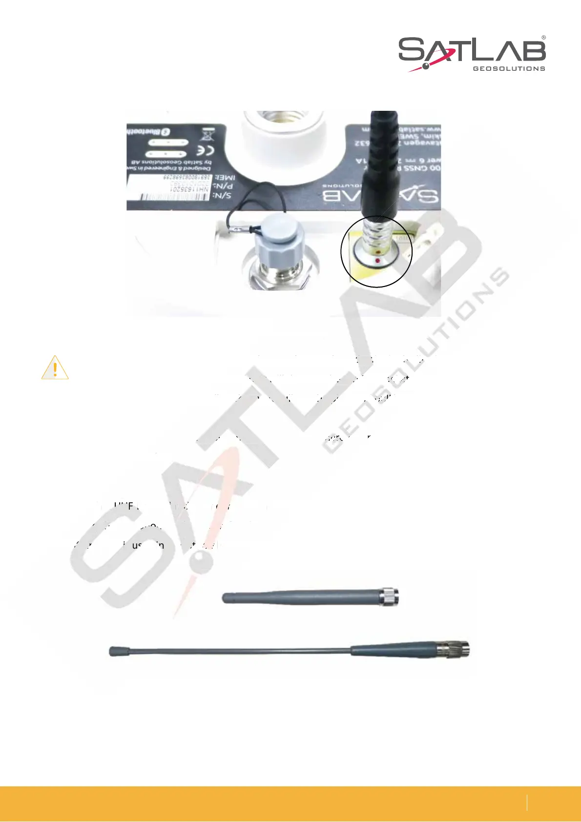
Figure 5-4 Five-pin plug
Figure 5-5 3G/GPRS antenna (above) & radio antenna (below)
Note: 1. When connecting the various plugs, make sure the red point in the line joint at the red
point in the receiver socket is aligned or it will damage the receiver socket and plugs.
2. Directly grasp the sliding collar when you pull out the plug, and pull hard. This will not rotate
the plug.
3. After using the cable, it should be put in a place where it cannot be squeezed to prevent
damage to the plug.
Antenna
5IFSFJTCPUIB6)'JOUFSOBMSBEJPBOUFOOBBOEB((134BOUFOOB:PVDBOTFMFDUUIFBQQSPQSJBUFBOUFOOB
according to the operation mode you prefer. The UHF radio antenna is used in the UHF mode, and the external
((134BOUFOOBJTVTFEJOUIFJOUFSOBM(4.NPEF
Fig
ure 5-4 Five-pin p
lug
o
us
p
p
lugs, make sure the re
d
d
d
po
o
o
int in t
he
he
he
l
inin
in
e
jo
in
al
ig
ne
d
or
o
i
t
t
t
wi
w
w
ll damage th
e
e
e
re
ce
ce
ce
i
iv
er s
oc
oc
oc
kekeke
t
t
t
an
d
g
collar
w
w
w
h
h
he
n
n
y
yo
yo
u
u
u
pupu
u
ll
l
l
out
t
t
he
he
he
p
p
p
lu
lu
lu
g, a
nd
nd
p
p
p
ululul
l
l
l
ha
rd
e
c
able,
it
t
t
s
ho
o
o
u
u
ul
d
be
be
b
p
ut
ut
ut
in a place
wh
wh
wh
ererer
e
e
e
it
it
it
c
an
h
e
plug.
P
UI
B
B
B
6)
6)
6)
'
'
'
JO
JO
J
UF
SO
BM
M
M
S
BE
E
E
E
BE
JP
BO
UF
UF
F
F
F
OO
O
O
O
O
B
B
O
E
B
((
13
d
in
g
to
to
to
t
t
he
he
he
ope
ra
a
a
ti
ti
ti
on
on
on
m
o
o
od
e
e
yo
u
u
u
u
pr
pr
pr
r
r
ef
er. The UH
F
(
(
13
3
3
4
4
4
BO
BO
BO
U
FOO
B
B
B
JT
JT
JT
VT
VT
VT
F
FE
JO
JO
JO
UI
I
I
F
F
F
JO
O
O
U
UF
UF
SO
SO
SO
SO
B
B
BM
B
B
(4
.
NP
E

Related product manuals