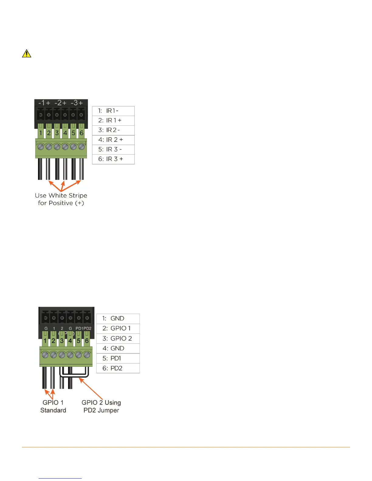
IR Wiring
IR connections are made using 6-pin Screw Down Plug-in Connectors supplied with matrix or receiver. The wire
slips into the hole and locks screw located at the top of the connector.
IMPORTANT! IR Wiring Precautions
•
Ensure that all IR emitters are within 15 feet (4.6 meters) from the controller’s location.
•
Use of 3rd party flashing IR emitters with Talk Back is not recommended. These types of emitters can draw voltage
away from the IR signal that can degrade IR performance.
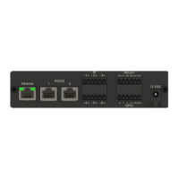
IR Connector Pinout
GPIO Wiring
General Purpose Input/Outputs (GPIO) are binary I/O ports used on Savant controllers to trigger an action within
the system. Events can control a device, such as turning on an amplifier (output) or detecting a state change for a
device (input) to perform a workflow. Pins 1-4 are used for input or output depending on configuration.
GPIO Pull Down Resistor (PD) Usage (Option)
The GPIO pins are by default configured as inputs and pulled high to +12V while the host is booting up. To pull the
GPIO signal low during a host reboot and/or power cycle, a jumper wire can be connected between a GPIO pin
and its corresponding PD1 or PD2 pin. Doing this adds a 1k ohm resistor between the GPIO pin and ground which
keeps the GPIO output below 0.8V while host is rebooting.
• Add jumper between GPIO 1 and PD1 to pull the
GPIO 1 pin low while host is rebooting.
• Add jumper between GPIO 2 and PD2 to pull
the GPIO 2 pin low while host is rebooting.
SmartControl 12 Controller Deployment Guide
Copyright © 2016 Savant Systems, LLC