25
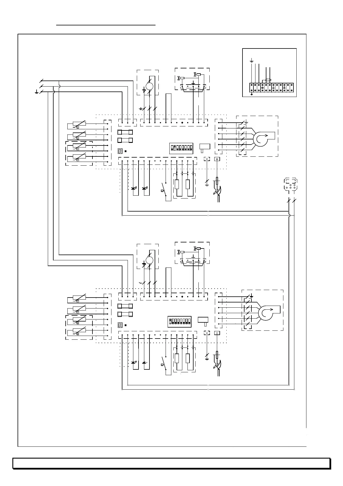
10.2 AMC 78 to 116 warm air heaters
Get: MW
Date: 07-2014
Auth:
Ver:a
Title:
Nr.:
R136
HR-series 80... 120
1 2 3 4 5 6 7 8
ON
10
S3
S2
N
L
1
2
3
1 2 3
J2
341 9 1 0 122 7
5
11 6
8
J4
1 2 3 4
1
2
3
4
5
6
1
5
4
2
3
M2.2
1
5
2
6
3
7
4
8
-T
20K@25°C
-T
20K@25°C
-T
20K@25°C
5 61211 13 144
7
M1.2
T2
J6
J12
J9
1 2 3 1098
Control unit 1
166HC
J7
F2
F1
2 x 5AT
R2 R3
2
5
4
1
-T
20K@25°C
-T
20K@25°C
flue / Abgas / fumée /
rookgas sensor
12 11
dP
1 2 3
J2
341 9 1 0 122 7
5
11
6
8
J4
1
2 3 4
1
2
3
4
5
6
1
5
4
2
3
M2.1
1
5
2
6
3
7
4
8
-T
20K@25°C
-T
20K@25°C
-T
20K@25°C
5 61211 13 144 7
M1.1
T2
J6
J12
J9
1 2 3 1098
Control unit 2
166HC
J7
F2
F1
2 x 5AT
R2 R3
25 4
1
-T
20K@25°C
-T
20K@25°C
13 14
dP
5
4
22°C
1 2 3 4 5 6 7 8
ON
10
S3
S2
1 2
5
43
L (230V AC)
22°C
12
11
13 14
FR
Sonde température
ambiante à l'aérotherme
LE D 1
rouge
(opt.)
LED 2
ve rt
(opt)
vert/jaune
bleu
marron
noir
vert / jaune
gris
rouge
vert\jaune
bleu
noir
blanc
jaune
orange
vert/jaune
bleu
noir
transparent
blanc
rouge
vert
protection thermique
de l'echangeur
Reconnaissance
de l'appareil
Ventilateur 2
vanne gas 2
Bruleur ventilateur
pressostat
LE D 1
rouge
(opt.)
LED 2
ve rt
(opt)
vert / jaune
bleu
marron
noir
vert / jaune
gris
rouge
vert / jaune
bleu
noir
blanc
jaune
orange
vert / jaune
bleu
noir
transparent
blanc
rouge
vert
Reconnaissance
de l'appareil
Ventilateur 1
vanne gas 1
Bruleur ventilateur
pressostat
Thermostat (bus)
Module 1: Position micro commutateur (S2) standard 1 sur
ON, et S3 sur 1.
Module 2: Position micro commutateur S2, 2 sur ON et S3
sur 0 (zéro)
En régulation centralisée
L'appareil 3 sur 8: position micro commutateur S2 sur 0
(zéro) et S3 sur 0 (zéro)
Neutaal
Thermostat (bus)
Installateur
mise à la terre
marron
marron
blanc
blanc
ve rt
jaune
flue / Abgas / fumée /
rookgas sensor
Sonde température
ambiante à l'aérotherme
protection thermique
de l'echangeur
marro n
marron
blanc
blanc
vert
jaune
Module 2
Module 1
To MULTITHERM
MULTITHERM
Burner fan 2
To connect by the installer
Gas valve 2
Main fan 2
Burner 2
of the main fan 2
sensors of the heat
exchanger 2
sensor of the
exhaust gases 2
Setting of the micro switches S2 and S3 : see
paragraphs 9.1 and 9.2
Ionisation/ignition
electrode 2
Appliance
identification 2
Pressostat 2
Rearming button 2
Burner fan 1
Gas valve 1
Main fan 1
Burner 1
of the main fan 1
sensors of the heat
exchanger 1
sensor of the
exhaust gases 1
Platine de contrôle 1
Appliance
identification 1
switch 1
Rearming button 1
Ionisation/ignition
electrode 1
Blue
Maroon
Maroon
Blue
Yellow/green
Yellow/green
Black
Blue
Blue
Black
Yellow/green
Black
Yellow/green
Blue
Maroon
Maroon
Maroon
Yellow/green
Yellow/green
Red
Transparent
White
Green
Yellow/green
Black
Blue
Black
Black
Blue
Yellow/green