6
5.1 Encoder or Connector ?
Programming
5 Programming
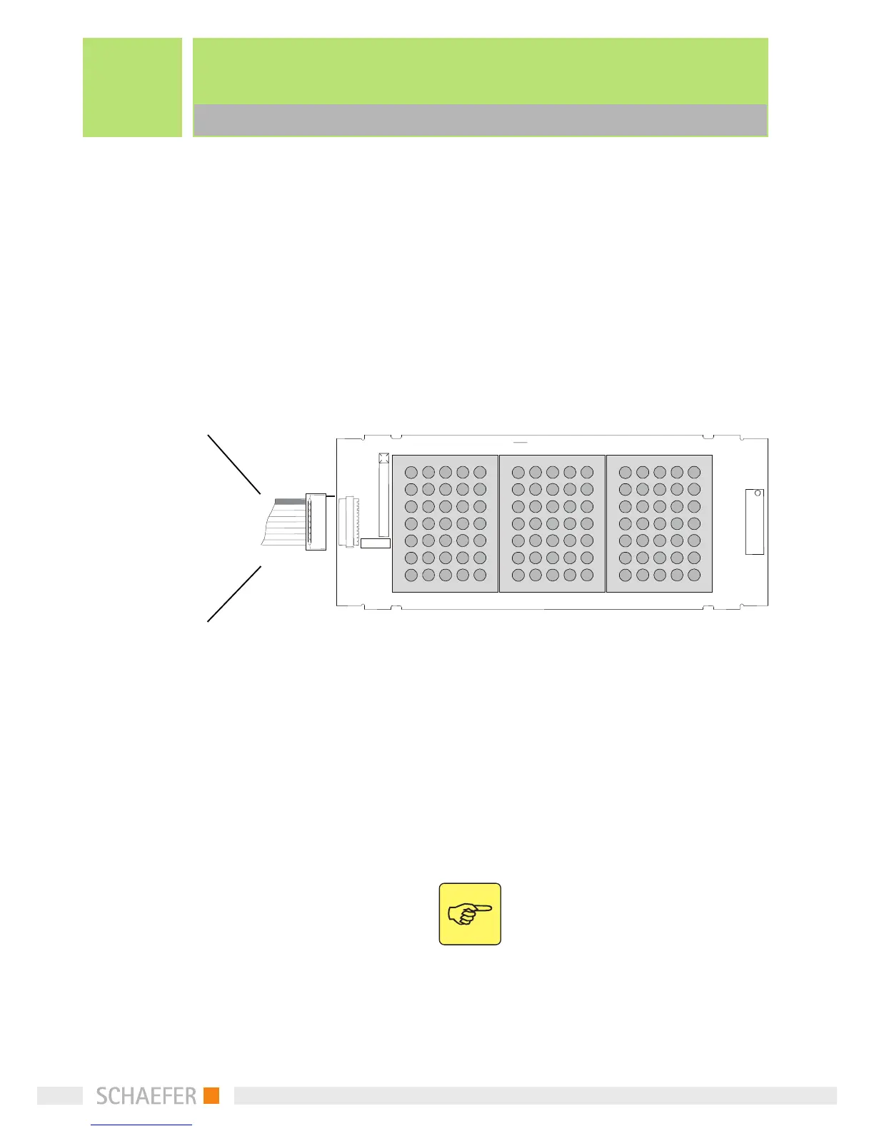
The pin configuration can be modified via PC (DMD-
Config-Kit). Please note that the configuration of the
encoder cannot be changed, especially if pins were
defined as special text.
Pin configuration
5.1 Encoder or Connector ?
The table below gives you a general idea when an En-
coder PCB or Connector PCB should be used.
Depending on the number of Floors, horizontally rol-
ling messages and type of arrows or travel signal used
will depend on whether a connector or encoder is re-
quired.
Note: More than two special texts are
only possible as from software version 2.6
on the DMD.
Travel
GND
Down
Up
Adr 4
Adr 3
Adr 2
Adr 1
Adr 0
V in
Pin
Pin
Pin
Pin
Pin
Pin
Pin
Pin
Pin
Pin
10
9
8
7
6
5
4
3
2
1