24
2019-03-06 / V1.0
Installation
Contactors CT/CU Series – Installation and Maintenance Instructions
3
4
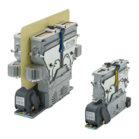
Fig. 18: CT/CU 1215/04, 1230/04, 1215/08, 1230/08:
Connect the coil control wires (4) to the cage clamp
terminals (3)
8
Fig. 19: CT/CU 1115/10/11, 1130/10/11: For contactor types
with plug and socket connectors, connect the plug to
the socket (8)
4
3
Fig. 20: CT/CU 1215/10/11, 1230/10/11: Connect the coil con-
trol wires (4) to the cage clamp terminals (3)
Reattach the protection caps
Depending on the contactor type, see Fig. 21 to Fig. 24 .
X
Fix the protection cap (3) of the auxiliary switches.
X
Screw in the 2 knurled thumb screws (5) and tight-
en them by hand force as tight as possible.
- Make sure that all the washers are close to the
knurled thumb screws (5).
- The washers must remain outside of the cover.
X
Fix the protection cap (4) of the coil terminal (4).
X
Screw in the the slotted-head screw (6) including
washers.
3
4
5
5
6
Fig. 21: CT/CU 1115/04, 1130/04, 1115/08, 1130/08:
Reattach the protection cap (3) of the auxiliary
switches and the protection cap (4) of the coil terminal
3
4
5
6
Fig. 22: CT/CU 1215/04, 1230/04, 1215/08, 1230/08:
Reattach the protection cap (3) of the auxiliary
switches and the protection cap (4) of the coil terminal
4
6
Fig. 23: CT/CU 1115/10/11, 1130/10/11: Reattach the protec-
tion cap (4) of the coil terminal
3
4
6
5
Fig. 24: CT/CU 1215/10/11, 1230/10/11: Reattach the protec-
tion cap (3) of the auxiliary switches and the protec-
tion cap (4) of the coil terminals
 Loading...