25
2019-03-06 / V1.0
Contactors CT/CU Series – Installation and Maintenance Instructions
Installation
Bundle and x the wires
Depending on the contactor type, see Fig. 25 to Fig. 28.
The xing lugs for the cable ties have a size of 7x2.5mm.
X
Use appropriate cable ties (9) and bundle and x
the wires as shown in the gures below.
9
7 x 2.5 mm
Fig. 25: CT/CU 1115/04, 1130/04, 1115/08, 1130/08:
Bundle and x the wires
9
7 x 2.5 mm
Fig. 26: CT/CU 1215/04, 1230/04, 1215/08, 1230/08:
Bundle and x the wires
9
7 x 2.5 mm
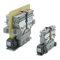
Fig. 27: CT/CU 1115/10/11, 1130/10/11: The auxiliary switch-
es of contactors with plug and socket connectors are
completely wired when shipped from the factory. For
these contactor types it is not necessary to bundle and
x the wires between connector and switches.
9
7 x 2.5 mm
Fig. 28: CT/CU 1215/10/11, 1230/10/11: Bundle and x the
wires
Reattach the upper module
Depending on the contactor type, see Fig. 29 to Fig. 32.
NOTICE
The modules are mechanically coded. Only one
mounting position is possible. Optical marks and
coding pins are provided to ensure the proper po-
sitioning.
X
Do not try to force the upper module into the
wrong position.
X
Attach the upper module in the correct position.
X
Make sure that all 4 latching levers (2) are in the
open position.
X
Check the correct position and put the upper
module (A) onto the lower module (B).
X
Close the 4 latching levers (2) one by one.
- Each of the 4 lock bars (1) must audible engage.
- Make sure that the 4 lock bars (1) have snapped
into place safely.
- The upper module must be xed tightly.
A
1
2
2
B
Fig. 29: CT/CU 1115/04, 1130/04, 1115/08/10, 1130/08/10:
Reattach the upper module (A) to the lower module (B)
 Loading...