35
2019-03-06 / V1.0
Contactors CT/CU Series – Installation and Maintenance Instructions
Maintenance
7
9
8
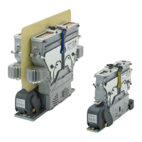
Fig. 48: CT/CU1215/10/11, 1230/10/11: Replace the moving
bridge 2
X
Carefully pull the moving double bridge (10) out
of the lower modules.
X
Remove the clip (11) and the plastic lever (12).
10
11
12
Fig. 49: CT/CU 1215/04, 1230/04, 1215/08, 1230/08:
Replace the moving bridge 3
10
11
12
Fig. 50: CT/CU 1215/10/11, 1230/10/11: Replace the moving
bridge 3
X
Attach the plastic lever (12) with a new clip (11) to
the new moving double bridge (10).
X
Insert the new moving double bridge (10) from
the top into the guidance.
X
Attach the 2 springs (9) to the spring holder (8).
X
Press and hold the spring holder (8) in place and
x it with the 2 screws including washers (7) using
a 4 mm hexagon socket wrench.
X
Thighten the 2 screws (7) with a torque of 2 Nm.
X
Screw on a new self-locking nut (M8 x 1.25) includ-
ing washer (1) at the bottom of the lower module
using a 13 mm socket wrench.
X
Thighten the self-locking nut (1) with a torque of
10 Nm.
X
Gently push the small lever (5) into the guidance
of the bigger one (6).
X
Test the new moving double bridge (10) by lifting
it up and down.
- The moving double bridge (10) must easily
move up and down.
X
Put the side cover (4) in place.
X
Fix the side cover with the 2 hexagon head screws
(M4) and washers (2) at the bottom.
X
Screw in the torx screw and the aluminium sleeve
(3) in the middle of the side cover (4) using a TX10
torx bit.
X
Thighten the torx screw (3) with a torque of 0.5Nm.
X
Secure the self-locking nut (1) again with red lock-
ing varnish.
 Loading...