36
2019-03-06 / V1.0
Maintenance
Contactors CT/CU Series – Installation and Maintenance Instructions
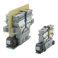
Remove the xed contacts
Depending on the contactor type, see Fig. 51 to Fig. 58.
X
Make sure that the latching levers are in the closed
position to avoid damage.
X
Put the upper module upside down on a work-
bench or table on a smooth surface.
Only for contactor types with heat sinks:
X
Remove the 2 xing screws including washers (5)
of each heat sink (6) using a TX20 torx bit.
X
Remove the heat sinks (6) from the xed contacts.
X
Remove the 4 xing screws including washers (1)
of the xed contacts (2) using an appropriate sock-
et wrench:
- 8 mm socket wrench (M5) for CT/CU 11xx/04,
CT/CU 12xx/04
- 10 mm socket wrench (M6) for
CT/CU 11xx/08/10/11, CT/CU 12xx/08/10/11
- 2 of the 4 screws are marked with red
locking varnish which will be destroyed
during that operation.
- 2 of the 4 screws are used to fasten the
cable lug with the copper wire.
X
Keep the screws and washers in a safe place.
X
If necessary, push the cable lugs (3) and the cop-
per wires slightly to the side.
X
Push both xed contacts (2) slightly to the centre
to meet the gap.
X
Remove the xed contacts (2) one by one.
1
1
2
3
3
2
Fig. 51: CT/CU 1115/04: Remove the xed contacts
1
2
1
2
3
3
Fig. 52: CT/CU 1130/04, 1115/08/10, 1130/08/10: Remove the
xed contacts
5
6
5
6
Fig. 53: CT/CU 1115/11, 1130/11: Remove the heat sinks
1
2
1
2
3
3
Fig. 54: CT/CU 1115/11, 1130/11: Remove the xed contacts
 Loading...