Instruction Manual for Electroblock EBL 241-2
12
Date: 16.07.2019 8110514 BA / EN
E Layout
21
4
10
3
5678
11
9
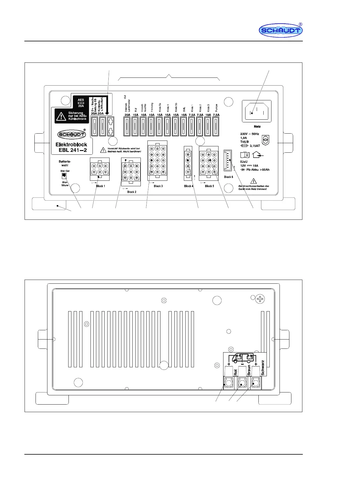
Fig. 4 Layout of the EBL 241-2 electroblock (front)
1 AES/compressor fridge f use
2 Flat vehicle fuses
3 Low power device socket, 230V AC mains connection
4 LT ... control and display panel connector
5 Connector block, light circuits 1 to 3
6 Connector block, D+, side marking lights battery sen-
sor/control line
7 Connector block, heating, circuits 4 and 5,
side marking lights, awning light
8 Connector block, multimedia (radio), pump
9 Connector block, fridge power supply,
step, fridge controller
10 Lead-gel / lead-acid battery changeover
switch
11 Attachment feet
123
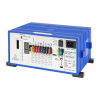
Fig. 5 Layout of the EBL 241-2 electroblock (rear)
1 Connection, living area battery
2 Earth connector
3 Connection, starter battery