25GB
• Before you press the ON/OFF switch check that the
saw blade is tted correctly. Moving parts must run
smoothly.
• Before you connect the equipment to the power sup-
ply make sure the data on the rating plate are dentical
to the mains data.
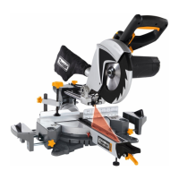
8. Attachment and operation
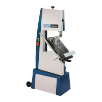
8.1 Attaching the saw (Fig. 1-6)
• To adjust the rotary table (16), push the locking lever
(13) downwards and pull the lower indexed position
lever (12) upwards with your index nger.
• Rotate the rotary table (16) and pointer (14) to the
desired angle on the scale (15) and lock in place by
folding up the locking lever (13).
• Pressing the machine head (5) lightly downwards and
removing the locking bolt (24) from the motor bracket
at the same time disengages the saw from the low-
est position.
• Swing the machine head (5) up until the release lever
(3) latches into place.
• It is possible to secure the clamping device (8) to the
left or right on the stationary saw bench (17).
• Attach the workpiece supports (9) to the xed saw
table (17) as shown in Figure 6a,b,c and push all the
way through. Secure the shafts with the retaining
springs to prevent them from slipping out accidentally.
The fasten in the desired position with the screw (10).
• It is possible to tilt the machine head (5) a max. 45° to
the left by loosening the set screw (22).
8.2 Precision adjustment of the stop for crosscut
90° (Fig. 3,5,18)
• No stop angle included.
• Lower the machine head (5) and secure using the
locking bolt (24).
• Loosen the set screw (22).
• Position the angle stop (a) between the saw blade (7)
and the rotary table (16).
• Slacken the counternut (d). Adjust the adjusting screw
(30) until the angle between the saw blade (7) and ro-
tary table (16) is 90°.
• Retighten the counternut (d) to secure this setting.
• Subsequently check the position of the angle indica-
tor. If necessary loosen the pointer (20) using a Philips
screwdriver, set to position 0° on the angle scale (19)
and re-tighten the retaining screw.
8.3 Precision adjustment of the stop for mitre cut 45°
(Fig. 1,3,5,19)
• No stop angle included.
• Lower the machine head (5) and secure using the
locking bolt (24).
• Fix the rotary table (16) in the 0° position.
• Loosen the set screw (22) and use the handle (1) to
angle the machine head (5) 45° to the left.
• 45° - position angle stop (b) between the saw blade
(7) and rotary table (16).
• Slacken the counternut (c). Adjust the adjusting screw
(31) until the angle between the saw blade (7) and ro-
tary table (16) is precisely 45°.
• Retighten the counternut (d) to secure this setting.
8.4 Cross cut 90° and turntable 0° (Fig.1,2,6,7)
In the case of cutting widths up to approx. 100 mm it is
possible to x the traction function of the saw with the
set screw (23) in the rear position. In this position the
machine can be operated in cross cutting mode. If the
cutting width is over 100 mm then it is necessary to en-
sure that the set screw (23) is loose and the machine
head (5) can move.
Attention! For 90° mitre cuts, the moveable stop rail (28)
must be xed in the inner position.
• Open the set screw (29) on the moveable stop rail (28)
and push the moveable stop rail (28) inwards.
• The moveable stop rail (28) must be locked in a po-
sition far enough from the inner position that the dis-
tance between the stop rail (28) and the saw blade (7)
is no more than 5 mm.
• Before making the cut, check that no collision could
occur between the stop rail (28) and the saw blade (7).
• Tighten the set screw (29) again. (2x 8.3 +8.4)
• Move the machine head (5) to its upper position.
• Use the handle (1) to push back the machine head
(5) and x it in this position if required (dependent on
the cutting width).
• Place the piece of wood to be cut at the stop rail (18)
and on the turntable (16).
• Lock the material with the clamping device (8) on the
xed saw table (16) to prevent the material from mov-
ing during the cutting operation.
• Push down the release lever (3) to release the ma-
chine head (5).
• Press the ON/OFF switch (2) to start the motor.
• With the drag guide (23) xed in place:
use the handle (1) to move the machine head (5) steadily
and with light pressure downwards until the saw blade (7)
has completely cut through the work piece.
• With the drag guide (23) not xed in place:
pull the machine head (5) all the way to the front.
Lower the handle (1) to the very bottom by applying
steady and light downward pressure. Now push the
machine head (5) slowly and steadily to the very back
until the saw blade (7) has completely cut through the
work piece.
• When the cutting operation is completed, move
the machine head (5) back to its upper (home)
position and release the ON/OFF button (2).
Attention! The machine executes an upward stroke
automatically due to the return spring, i.e. do not re-
lease the handle (1) after completing the cut; instead
allow the machine head to move upwards slowly whilst
applying light counter pressure.
8.5 Cross cut 90° and turntable 0° - 45° (Fig. 1,6,7)
The crosscut saw can be used to make crosscuts of 0°
-45° to the left and 0° -45° to the right in relation to the
stop rail.
 Loading...