Appendix C - Mechanical Installation
50
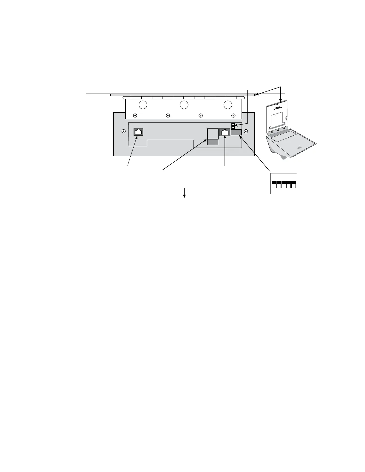
Wiring Connections
Once the HandPunch is attached to the wall plate the wiring connections to the
HandPunch can be made (see Figure 12-4).
WALL
ON
OFF
5 4 3 2 1
Serial RS-232
RJ-45 Jack
Optional Modem
Dip Switches
Wall Plate
Top of
Terminal
Top of HandPunch
Power
Connectors
J7 Battery
Jumper
Figure 12-4: Wiring Connections and Dip Switches
Table 10 on page page 51 provides the pinouts for the RJ-45/RS-232 Serial Host Computer
Connection.
Figure 12-5 on page page 51 provides a diagram of the RJ-45/RS-232 Connector.
Figure 12-6 on page page 52 provides a Host PC to HandPunch Modem Network wiring
diagram (Modem wiring is a HandPunch option).
Wiring
Examples
 Loading...