2
Operating instructions
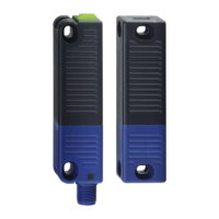
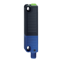
Safety sensor
RSS 36
EN
The information contained in this operating instructions manual is
provided without liability and is subject to technical modifications.
There are no residual risks, provided that the safety instructions as well
as the instructions regarding mounting, commissioning, operation and
maintenance are observed.
1.6 Warning about misuse
In case of improper use or manipulation of the safety
switchgear, personal hazards or damages to machinery
or plant components cannot be excluded. The relevant
requirements of the standard ISO 14119 must be observed.
1.7 Exclusion of liability
We shall accept no liability for damages and malfunctions resulting from
defective mounting or failure to comply with this operating instructions
manual. The manufacturer shall accept no liability for damages
resulting from the use of unauthorised spare parts or accessories.
For safety reasons, invasive work on the device as well as arbitrary
repairs, conversions and modifications to the device are strictly
forbidden, the manufacturer shall accept no liability for damages
resulting from such invasive work, arbitrary repairs, conversions and/or
modifications to the device.
2. Product description
2.1 Ordering code
This operating instructions manual applies to the following types:
RSS 36
➀
-
➁
-
➂
-ST with 8-pin connector
No. Option Description
➀
Standard coding
I1
Individual coding
I2
Individual coding, re-teaching enabled
➁
D
With diagnostic output
SD
With serial diagnostic function
➂
Without latching
R
With latching, latching force approx. 18 N
RSS 36
➀
-
➁
-
➂
-ST5 with 5-pin connector
No. Option Description
➀
Standard coding
I1 Individual coding
I2 Individual coding, re-teaching enabled
➁
without diagnostic function (on request)
D With diagnostic output
➂
Without latching
R With latching, latching force approx. 18 N
Actuator
RST 36-1 Without latching
RST 36-1-R
With latching, latching force approx. 18 N
2.2 Special versions
For special versions, which are not listed in the order code below 2.1,
these specifications apply accordingly, provided that they correspond to
the standard version.
2.3 Comprehensive quality insurance to 2006/42/EC
Schmersal is a certified company to appendix X of the Machinery
Directive. As a result, Schmersal is entitled to autonomously conduct
the conformity assessment procedure for the products listed in
Appendix IV of the MD without involving a notified body. The prototype
test certificates are available upon request or can be downloaded from
the Internet at www.schmersal.com.
2.4 Purpose
This non-contact, electronic safety sensor is designed for application in
safety circuits and is used for monitoring the position of movable safety
guards. In this application, the safety sensor monitors the position of
hinged, sliding or removable safety guards by means of the coded
electronic actuator.
The safety function consists of safely switching off the safety outputs
when the safety guard is opened and maintaining the safe switched off
condition of the safety outputs for as long as the safety guard is open.
The safety switchgears are classified according to
ISO 14119 as type 4 switching devices. Designs with
individual coding are classified as highly coded.
Safety sensors and actuators with latching (ordering suffix 'R') must
always be used in pairs. The latching force (approx. 18 N) exercised by
the permanent magnet keeps hatches and small guards closed, also in
a de-energised condition.
The system can be used as a door end stop up to 5 kg at 0.25 m/s.
The diagnostic output of the safety sensor alternatively can be used
as a conventional output or as a “serial output“ with input and output
channel.
Series-wiring (only 8-pin version)
Series-wiring can be set up. Response and risk times remain
unchanged by series-wiring. The number of components is only limited
by the external cable protection according to the technical data and
the line loss. Series-wiring of up to 31 RSS 36 … SD components with
serial diagnostics is possible.
In devices with the serial diagnostics function (ordering suffix -SD), the
serial diagnostics connections are wired in series and connected to a
SD Gateway for evaluation purposes.
Wiring examples for series-wiring, refer to appendix.
The user must evaluate and design the safety chain in
accordance with the relevant standards and the required
safety level. If multiple safety switchgears are involved in
the same safety function, the PFH values of the individual
components must be added.
The entire concept of the control system, in which the safety
component is integrated, must be validated to the relevant
standards.
2.5 Technical data
Standards: IEC 60947-5-3, ISO 13849-1, IEC 61508, IEC 62061
Enclosure: glass-fibre reinforced thermoplastic, self-extinguishing
Working principle: RFID
Frequency band: 125 kHz
Transmitter output: max. –6 dBm
Coding level according to ISO 14119:
- I1-version: high
- I2-version: high
- Standard coding version: low
Actuator: RST 36-1, RST 36-1-R
Fixation sensor / actuator: 2 x M4 cylinder head screw
with washers to DIN 125A / form A
Tightening torque of the fixing screws: 2.2 … 2.5 Nm
Series-wiring
(only 8-pin version): Number of devices unrestricted,
observe external wiring protection,
max. 31 devices with serial diagnostic
Termination:
- ST: Connector plug M12, 8-pole, A-coded
- ST5: Connector plug M12, 5-pole, A-coded