6
Operating instructions
Safety sensor
RSS 36
EN
6. Diagnostic functions
6.1 Operating principle of the diagnostic LEDs
The safety sensor indicates the operating condition and faults by means
of three-colour LEDs located in the lateral surfaces of the sensor.
The following LED indicators are the same for safety
sensors with conventional diagnostic output as for those
with a serial diagnostic function.
The green LED indicates that the safety sensor is ready for operation.
The supply voltage is on and all safety inputs are present.
Flashing (1Hz) of the green LED signals that a voltage is missing on
one or both of the safety inputs (X1 and/or X2).
The yellow LED always signals the presence of an actuator within
range. If the actuator is operating near the limit of the hysteresis range
of the safety sensor, the LED is flashing.
The flashing can be used to prematurely detect variations in the
clearance between the sensor and the actuator (e.g. sagging of a safety
guard). The sensor must be adjusted before the distance to the actuator
increases and before the safety outputs are disabled, thus stopping the
machine. If an error is detected, the red LED will be activated.
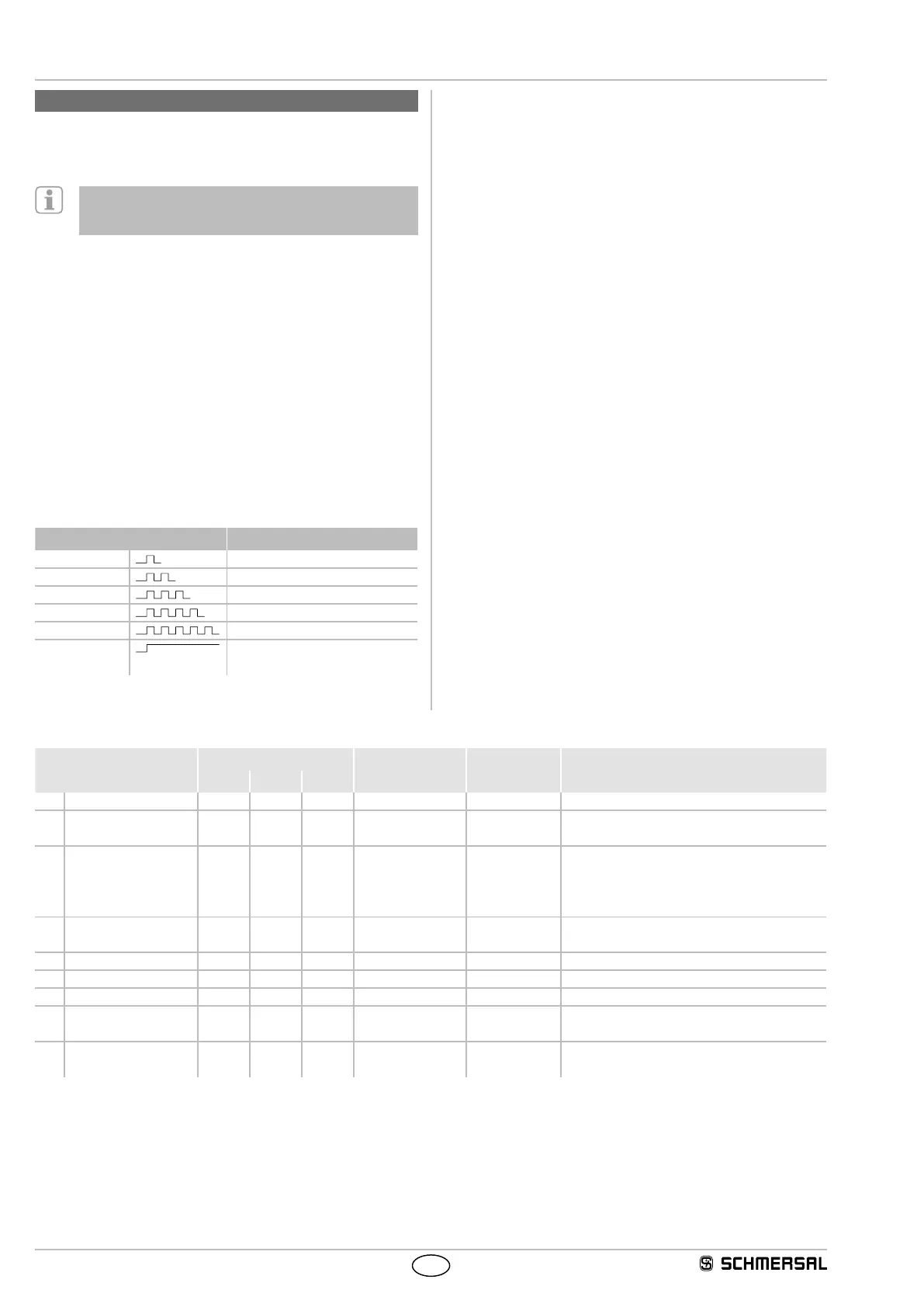
Flash codes red diagnostic LED
LED indication (red) Error cause
1 flash pulse Error output Y1
2 flash pulses Error output Y2
3 flash pulses Cross-wire Y1/Y2
4 flash pulses ambient temperature too high
5 flash pulses Wrong or defective actuator
Continuous red Internal fault, with yellow flashing
teaching procedure
6.2 Operating principle of the electronic diagnostic output
A diagnostic output additionally indicates the operating condition
(refer to table 1). These signals can be used in a downstream control.
The short-circuit proof diagnostic output OUT can be used for central
visualisation or control functions, e.g. in a PLC. It indicates the
switching condition as shown in the table 1.
Error
Errors, which no longer guarantee the function of the safety sensor
(internal errors) cause the safety outputs to be disabled within the risk
time. Any error that does not immediately affect the safe functionality of
the safety sensor (e.g. the ambient temperature too high, interference
potential at a safety output, cross-wire short) will lead to a delayed
shut-down (refer to table 2).
After the rectification of the error, the error message is reset by opening
the corresponding safety guard.
Error warning
The diagnostic output can also be used to detect clearance variations
between the sensor and the actuator in the same way as the yellow
LED. An active fault causes the diagnostic output to be disabled. The
safety outputs are disabled after max. 30 minutes if the fault is not
rectified. This signal combination, diagnostic output disabled and safety
channels still enabled, can be used to stop the production process in a
controlled manner.
Table 1: Examples of the diagnostic function of the safety-sensor with conventional diagnostic output
Sensor function LEDs Diagnostic output Safety outputs Note
Green Red Yellow Y1, Y2
I. Supply voltage On Off Off 0 V 0 V Voltage on, no evaluation of the voltage quality
II. actuated Off Off On 24 V 24 V The yellow LED always signals the presence of
an actuator within range.
III. Actuated in limit area Off Off Flashes
(1Hz)
24 V
pulsed
24 V The sensor must be adjusted before the
distance to the actuator increases and before
the safety outputs are disabled, thus stopping
the machine.
IV. Error warning,
sensor actuated
Off Flashes Off 0 V 24 V After 30 minutes if the error is not rectified
V. Error Off Flashes Off 0 V 0 V Refer to table with flash codes
VI. Teach actuator Off On Flashes 0 V 0 V Sensor in teaching mode
VII. Protection time Flashes Off Off 0 V 0 V 10 minutes pause after re-teaching
VIII. Error in input circuit
X1 and/or X2
Flashes
(1Hz)
Off Off 0 V 0 V Example: door open; a door in the safety circuit
upstream is also open.
IX. Error in input circuit
X1 and/or X2
Flashes
(1Hz)
Off On 24 V 0 V Example: door closed, a door in the safety circuit
upstream is open.